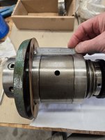
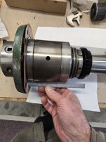
Actually spindle bearings are ok but the left side pair of bearing inner one is spinning freely now as it was difficult to get the spindle started to come until the right hand outside bearing cleared the casting. Something appears to be pinched as the LH threading gear is tight now and has no freeplay while sitting static. I surely thought it did as the RH one does. I described all this above and wasn't sure where to start looking as there is not marks on the spindle that indicate a problem and we only extracted to the right and never went left (back in). The sleeve EE-1125 spins freely and slides in/out till it touches, EE-2305. Hope that makes some sense. Thanks for your input and advise on the bearings, made need a left hand set (hope not).
How to install the app on iOS
Follow along with the video below to see how to install our site as a web app on your home screen.
Note: This feature may not be available in some browsers.
You are using an out of date browser. It may not display this or other websites correctly.
You should upgrade or use an alternative browser.
You should upgrade or use an alternative browser.
10ee Spindle weep hole leaking / revisit....
- Thread starter Zap921
- Start date
- Replies 49
- Views 2,495
Cal Haines
Diamond
- Joined
- Sep 19, 2002
- Location
- Tucson, AZ
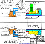
Here's my color-coded detail of the rear spindle bearing, etc., for the single-sight-glass headstock:... Something appears to be pinched as the LH threading gear is tight now and has no freeplay while sitting static. I surely thought it did as the RH one does. I described all this above and wasn't sure where to start looking as there is not marks on the spindle that indicate a problem and we only extracted to the right and never went left (back in). The sleeve EE-1125 spins freely and slides in/out till it touches, EE-2305. Hope that makes some sense. Thanks for your input and advise on the bearings, made need a left hand set (hope not).
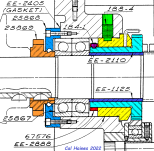
Maybe in the process of sliding the spindle out, the threading gear assembly got shifted to the right, such that the retaining ring 67576 (red) is rubbing against sleeve bearing EE-2888 (yellow)? Did spacer EE-1125 (blue) come out with the spindle or stay with gear EE-2110 (cyan)?
Hi Cal, EE-1125 stayed with the gear. It slides freely in/out of EE-2110 at this time and will stop when it touches the EE-2305. You can tell that something shifted a bit to the right with the withdrawal of the spindle because the setscrew 188-4 was tight to remove and wasn't that way prior to the removal. How would one even get to the other setscrew, 184-1? The hole in EE-2888 is what was binding the setscrew 188-4. With those tolerances in there it wouldn't take much to pinch something. Do those copper oil lines which gravity feed oil through EE-2888 just a slight press fit and wiggle out? Two roads right now that I see.
1. Clean everything up put new gasket on the front bearing retaining ring and reseat the spindle back in and see if that moves it back the tiny amount needed to free things up. I would have to extract it back out a bit then to make sure that inside bearing was turning freely again.
2. Try to take the threading gear and surrounding parts out to assess what happened and amount of damage.
All input from anyone and everyone is more than welcome. I'm definitely not in any hurry.
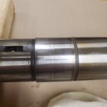
RimCanyon was correct about the reason for the sludge in the front cavity. That Monarch had sat in an uninsulated garage for the better part of 3 years here in Northern Ohio. I'm sure it got it's share of condensation moisture especially spring time every year. That could have also been a factor in the reason something didn't want to release the spindle under a normal load (whatever that it is)..... it moved with ease after that binding ceased. If you look at the spindle closely where the two back bearings were seated the inside edges of the races could have been where some resistance was at. Take a look at the drag marks running parallel to the spindle where the two back bearings were seated on the spindle. I just noticed these.

tailstock4
Cast Iron
- Joined
- Mar 3, 2013
- Location
- Oklahoma, USA
I have a 1968 10EE that I changed the spindle bearings in. I was curious if when you pulled the spindle did you release tension on both the front and rear bearings and then reseat them. This releases some of the tension or expansion on the rear bearings on the spindle and the front bearings on the casting bore.
By the way when you go back with these bearings, you’ll want to only tighten them up enough to hold the spacers in their correction position and then fully tighten when the spindle is in place.
A couple things I found that helped when going back with the spindle were to 1) heat the headstock and 2) a use a jig to hold the spindle. To warm the headstock I used a light bulb, wrapped the headstock in a blanket and left it overnight. This provided some expansion of the bearing bores easing installation.
When I went back with the spindles on both my 10EE and Rivett 1020S, I built a jig to hold the spindle. It was just three pieces of 1” pipe and 2 elbows. This makes a “C” shape. I then used my overhead gantry and a couple of heavy-duty long shock cords attached to the upper section of the “C”. The idea was to get the spindle in sort of a neutral buoyancy. This allows you to free up your hands to help make sure things line up correctly when they go back together. It is easy for things to get hung up.
On the front bearings there is a back labyrinth seal (part # 26118). On the outside of the non-rotating seal, there is an O-ring (part # 1191-46). There is also a set screw (part # 183-3) that locates this seal. I would recommend changing this O-ring, especially if you disturb this seal. This O-ring and labyrinth act as a dam for the oil and keep it from leaking back to the headstock reservoir. If it does leak, it will allow the oil to drain out which will then require a longer period for the oil to be refilled when the lathe is first started. On my machine the rear bearing gasket was original as I was the first person in the headstock. The oil return hole in the headstock casting was blocked by this gasket which prevented the oil from returning as it should have. Instead, it overflowed through the bearings. This in turn caused the labyrinth seal to be overwhelmed with oil which then leaked out the back. This problem was evident when I first acquired the machine. The new gasket from Monarch had the hole in the gasket as it should have been.
The accuracy of these machines depends a great deal on cleanliness as was stated before, correct bearing location in regard to the high marks, and also attention to the bearing spacers. Their parallelism and correct height in relation to each other are critical. On my machine because I went back with new bearings, I added .0002 of preload by under grinding the inner spacer. If all this is right, you can get some pretty low runout numbers.
Cal Haines
Diamond
- Joined
- Sep 19, 2002
- Location
- Tucson, AZ
Zap,
If you can get the spindle clutch (EE-2305) out without messing up the oil lines, you might try rigging something up to put a little pressure on the clutch gear assembly and see if you can pull it back to the left; maybe that will free it up. If that doesn't do it, I would probably want to pull the clutch gear assembly out and see what's wrong.
Pulling the L.H. Clutch Gear assembly out doesn't require taking out the idler gear (EE-1099) or anything on the idler gear stub shaft. Removing just the spindle clutch and shifter fork (EE-1102) will allow enough space for the clutch gear assembly to move right (towards the tailstock), then up and out. Grant's epic thread shows how, starting at post #468; note that he pulled the R.H. Clutch Gear (EE-2111) assembly first, starting at post #465, but I don't think that's necessary.
I don't know how the oil lines work or how they feed into the passages in the headstock; I was hoping you could tell us. Could you post some photos of how the oil line for the front bearings gets through the center cavities, to line up with the horizontal hole (the one drilled in from 3 O'clock on the spindle nose)? What does the end of the passage that dumps into the front spindle bearing cavity look like? Does it pass through a cored space, or did they somehow drill a cross hole?
What's the serial number and build date of your machine?
The set screw, 183-3, must be stripped out as I can't find any hex key that fits it and can't get a good look at what's at the bottom. It is securely in place and doesn't wiggle at all under finger pressure.On the front bearings there is a back labyrinth seal (part # 26118). On the outside of the non-rotating seal, there is an O-ring (part # 1191-46). There is also a set screw (part # 183-3) that locates this seal. I would recommend changing this O-ring, especially if you disturb this seal.
Cal, the last picture in Post #17 shows a smaller hole at about 3 o'clock. That hole is drilled at an upward angle straight back through the casting to the center cavity. The exit hole for the oil to the front bearing cavity is then drilled to intersect that, 3 o'clock inside the front cavity righthand wall looking through the nose. The oil line that feeds that is pictured in Post #12. 2nd oil line right to left coming out the oil sump.Makes a 90 degree right turn catching that hole drilled from the front of the casting. Hopefully someone has tried to remove some of those copper oil lines and will chime in. The large oil return in the front casting on the left side back wall, 7 o'clock, doesn't appear to be documented in the drawings. It's actually a counterbore type hole which chokes down to a smaller diameter exit hole before it opens to the center cavity. Any other pics you need Cal, just let me know.I don't know how the oil lines work or how they feed into the passages in the headstock; I was hoping you could tell us. Could you post some photos of how the oil line for the front bearings gets through the center cavities, to line up with the horizontal hole (the one drilled in from 3 O'clock on the spindle nose)? What does the end of the passage that dumps into the front spindle bearing cavity look like? Does it pass through a cored space, or did they somehow drill a cross hole?
Thank you guys for your input!
Cal Haines
Diamond
- Joined
- Sep 19, 2002
- Location
- Tucson, AZ
I can't tell how deep the cavity for the tachometer gear is cast. Does the oil passage go behind the cavity, or does the copper line have to travel through the cavity?
It must have been a fun bit of machining to hit an 1/8"(-ish), sloping oil passage with a cross-drilled hole. If possible, could you slide a couple of rods into the 3 O'clock oil passage and the cross hole, to show their angles? Or does the cross hole get drilled in from the back of the headstock and plugged?
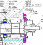
Can you verify that the front bearing oil return passage at 6 O'clock goes upward, into the recess between the front bearings, as show in this drawing (highlighted with blue):

On older versions of the headstock, the 6 O'clock hole travels horizontally, dumping out in the cavity for the tachometer gear.
Have you probed the depth of the hole for setscrew 183-3* to make sure the setscrew is actually there? If it helps, 183-3 is a 10-24x3/8 dog-point setscrew. The standard drive size for that screw is 3/32".
* for anyone that's not sure what we're talking about, this is the setscrew that retains the outer half of the front labyrinth oil seal (part #26118).
It must have been a fun bit of machining to hit an 1/8"(-ish), sloping oil passage with a cross-drilled hole. If possible, could you slide a couple of rods into the 3 O'clock oil passage and the cross hole, to show their angles? Or does the cross hole get drilled in from the back of the headstock and plugged?
Can you verify that the front bearing oil return passage at 6 O'clock goes upward, into the recess between the front bearings, as show in this drawing (highlighted with blue):
On older versions of the headstock, the 6 O'clock hole travels horizontally, dumping out in the cavity for the tachometer gear.
Have you probed the depth of the hole for setscrew 183-3* to make sure the setscrew is actually there? If it helps, 183-3 is a 10-24x3/8 dog-point setscrew. The standard drive size for that screw is 3/32".
* for anyone that's not sure what we're talking about, this is the setscrew that retains the outer half of the front labyrinth oil seal (part #26118).
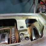
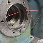
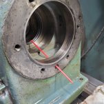
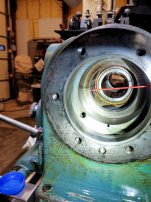
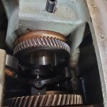
Here ya go Cal.. The first pic is of the oil line getting from the sump to feeding the front bearing cavity. There is a cavity in the casting where the oil line takes a 90 degree right and then goes to the front cavity wall. The hole is evidently drilled from the front face out the backside of the front cavity wall. 2nd pic shows how they connect but don't judge the angle on the interior plastic straw. I can move the front straw with the interior one. 4th shows the main drain to center cavity with counterbore, must maintain a certain level of oil in front cavity. Last one, thanks to your advice, spindle clutch is out. Oil lines are just a snug press fit and came out with not much effort. Is there anything other than 25869 and EE-1125 that hold the back bearings in place? Can the back bearings come out the back with damage to them? And now should the whole left hand thread gear and assembly slide out to the right? I'm trying to visualize what would push the inner bearing back a bit if it got dragged a bit and pinched (if that's possible) because nothing in the drawing touches it except the sleeve and that's only the inner race. Sure do appreciate the help.


rimcanyon
Diamond
- Joined
- Sep 28, 2002
- Location
- Salinas, CA USA
ZAP, do you have the owners manual from Monarch for your machine? Reason I ask is that it should have come with drawings that show all of the routing of oil lines in the headstock. If you don't have a drawing like that, suggest you give a call to Scott@Monarch, and ask him to dig up the drawings and send a copy. Maybe you can spend some time talking it over with him and let us all know what you find out.
Will do, the only reason I didn't get the manual from them when I first got this was all my electronics had been replaced during the time that New Departure had the lathe. Probably have to get it from them just for the reasons you mention. I have to order some gaskets and other things anyway.
Cal Haines
Diamond
- Joined
- Sep 19, 2002
- Location
- Tucson, AZ
Zap,
Thanks for the photos. I have more to say/ask about them later, when I have more time.
Grant removed his L.H. Clutch Gear (LHCG) after first removing his rear spindle bearings. To do that, he used a puller against the inner race of the right-rear bearing. Instead, I think I would try to come up with a way to pull the LHCG by grabbing the gear and pulling to the right (towards the tailstock). Maybe some sort of custom-made, C-shaped puller with fingers that get behind the gear?
Update: Spindle is waiting to be put back in after gaskets come in from Monarch. It appears as though the inner bearing on the rear set had gotten out of alignment and was the sticking point while removing the spindle. This caused the pinched gear, EE-2110, and the inner race on the bearing to also bind up. I speaking with Monarch, Cal, and my friend, Steve, measurements were taken from the print and compared to the sleeve and gear position on my lathe. It was apparent that EE-2110 and sleeve, EE-1125, were approximately 1/16" to far towards the tailstock and not completely seated. A jig was made to compress the sleeve first which was sticking out a little farther than the gear. It was compressed until it met the face of the gear at which time this allowed the pinched gear and inner bearing race to now turn freely. After that the gear and bronze bearing sleeve, EE-2888, were compressed until 2888 was seated against the headstock casting. The gears all turn freely now and the setscrew, 188-4, seat to it's normal depth with no binding. A little more cleaning inside to do and then back together it goes sometime probably next week. If anyone needs a picture of something, now is the time.
A big thanks to all that contributed to this endeavor, especially Cal, Daryl, Steve, and RimCanyon!! I'm one happy camper right now
A big thanks to all that contributed to this endeavor, especially Cal, Daryl, Steve, and RimCanyon!! I'm one happy camper right now
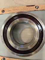
Well, was all cleaned up, gaskets on, and went to install the spindle this morning. Everthing went smoothly until about the last 19/32 (visual on scale). Again it bound up to the point it didn't push it any further. I was using the tailstock with a piece of 4x4 to push it in. Inside casting was heated for several hours (front & back where bearing are or go) and the spindle was left inside the unheated barn over night, 15 degrees for a low this morning. Pulled the spindle back out, LH hand threading gear bound up again. I wasn't sure where the exact stick point was so I took it apart again, 2x oil lines, 2305, 1102, and 1125. The sleeve slides nicely on the spindle all the way up to it's stop. Took the back retaining plate, 25868, off to get a visual on the back bearings. With nothing to interfere with the spindle except front and rear bearings, I tried another install of the spindle. Everything went smoothly with the spindle pushing the outside rear bearing out (so I removed it with photo below). At about the same point, 19/32, the spindle seized up again and this is about exactly where the front outside bearing race enters the casting. The inside rear bearing was coming out also with spindle but stopped at the 19/32 spot. I appears that the front outside bearing is our sticking point at this time (the front rear bearing race is already 3/4 it's width into the back side of the casting when the front touches) . Any ideas from anyone on why this last 1/2 inch going in and out of the spindle binds up? Any comments on the type of bearing used for the rear set in the picture. Both rear bearings were installed with the thrust side facing each other, fyi. Anything that can be misaligned on the front set of bearings?
Thanks,
Nick
Thanks,
Nick

rimcanyon
Diamond
- Joined
- Sep 28, 2002
- Location
- Salinas, CA USA
It's hard to diagnose problems like this from a distance.
When I have installed 10EE spindles in the past I use a piece of ⅝ or ¾ all thread, and I have machined spacers for each end, i.e. the spacers fit around the opening on the back of the headstock (and get added to as the spindle slides in) and into the front of the spindle. As much as possible I push the spindle in by hand, and if it gets slightly stuck I tap it with a soft face mallet or lead hammer. The rear bearing acts as a guide to keep the spindle aligned. I have never needed to use much force to get the spindle to slide home.
When I have installed 10EE spindles in the past I use a piece of ⅝ or ¾ all thread, and I have machined spacers for each end, i.e. the spacers fit around the opening on the back of the headstock (and get added to as the spindle slides in) and into the front of the spindle. As much as possible I push the spindle in by hand, and if it gets slightly stuck I tap it with a soft face mallet or lead hammer. The rear bearing acts as a guide to keep the spindle aligned. I have never needed to use much force to get the spindle to slide home.
Cal Haines
Diamond
- Joined
- Sep 19, 2002
- Location
- Tucson, AZ
Perhaps the labyrinth seal halves for the front bearing pair are interfering? If you think the right-front bearing is interfering with the headstock casting, put an indicator on its OD and rotate the spindle, see if it's running out.
It's troublesome that inserting/removing the spindle is causing the LH Clutch Gear and its bushing (EE-2888) to bind up. There should be clearance between the bushing and the spacer sleeve (EE-1125). Try putting the sleeve in by itself and see if it's got sufficient clearance. If you have a dial bore gauge you might try measuring the ID of the bushing and compare that to the OD of the sleeve. You already tried putting the spindle in without the sleeve (EE-1125) so we know that it isn't involved in the interference. So that leaves you with either the labyrinth seal or the right-front bearing.
If you can get the right-rear bearing out without exerting much pressure on the inner race, I would do that, then pull the clutch gear assembly out to the right. Take it apart and see why it's binding up. You have to slide the reverse idler gear (EE-1099) to the right to allow the clutch gear to come out.
Having the thrust sides of the outer races for the rear spindle bearings (25867) facing looks correct to me, based on the above drawing.
Note: Ignore the cyan (light blue) shaded oil return line in the first drawing, it isn't correct for this headstock.
rimcanyon
Diamond
- Joined
- Sep 28, 2002
- Location
- Salinas, CA USA
Zap, the outer spacer is free floating. If you tap it with your lead hammer on the high side it is easy to adjust. I don't think it is the problem per se. Did you tighten the castellated nut that holds the bearing assembly together? If not, that might be the problem, since the spacer could be loose enough to move easily. I don't think you need to worry about over-tightening that nut - the spacers are ground to give the correct pre-load.
No, I never messed with that nut. I'll check and see if it does move around, that would be kinda dissappointing if that's not my problem on the last half inch. You're probably right, just got to excited that it could be that easy of a fix. How would I know that the MRC rear bearings are the correct ones? You think those are the original rear bearings? thanks....
rimcanyon
Diamond
- Joined
- Sep 28, 2002
- Location
- Salinas, CA USA
Do a search on the forum for angular contact rear spindle bearings. There have been several threads.
Similar threads
- Replies
- 11
- Views
- 746
- Replies
- 8
- Views
- 557


