What's new
What's new

Best practice for work offsets and CAM programming

What software do you use that if you were to set Z zero at the bottom of the part you need to set every retract and clearance plane every time?

Meh, you are correct. CAM does take care of the proper clearance and plunge planes, but can we at least agree that if Z0 is set at the top of the part, it is easier and more obvious to read the rapid moves to make sure they do in fact clear?
If you have a clamp for example that is borderline at your rapid plane. Just slap a 1" block on top of your Z0 and eyeball it to be sure.

As far as where to set Z, I go both ways as I see fit, so no argument from me.
 
I like tool presetters (or just use them for measuring, now that we have offsets) but why d you say it limits you to any particular way ? Just do a little more arithmetic and you can still use any method you want.

I’ve seen some old school shops touching off every tool on the top of the part. When they change jobs they have to touch off the tools again.

And some new shops with rienshaw tool setters on every machine. Which is basically doing the same thing as a tool setter but taking up time and space on the machine.

At least with the tool setter it’s a one time purchase. And you can have standard tools loaded at anytime that will work with any known work offset. When a tool is going bad run that last part and set up another holder.

Tool setters are just the most efficient method I’ve found…. Not having one doesn’t limit a person, it just takes up more of there time
 
We had a Zoller optical pre setter connected to the 200 tool ATC on the Makino A77. Worked great until a 6 foot fluorescent diffuser came loose landed on it. A height gauge is not a pre setter if you are working to microns.
 
I’ve seen some old school shops touching off every tool on the top of the part. When they change jobs they have to touch off the tools again.
I wasn't arguing against you on the value of presetter - I just meant that they aren't limited to either z setting method, you can just do a little offline arithmetic if you want to use the other method.

They don't, by the way, have to touch off all the tools again, should be able to just change an offset, the relation between the tools remains the same. But some people like to do things the hard way ...

Can we insert a plug for the Millabrator here ? :D
 
See, by yourself that's fine but if you had other people in the shop it'd be asking for trouble.
Nope, I am not by meself, and the secret lies in the program header.
Not only on the setup sheet, but also in the program header there is a clear definition of where the X, Y and Z datums are.
If there is something unusual about the setup, it is noted in the header and so are the "gotcha" things.

But, I do agree that a fresh-through-the-door setup guy would need to be brought up to speed as to the nuances of what/how we do things here.
 
You've got better luck with The Help than I have ever had. I congratulate you :)
Fair 'nuff, I do have that luck on my side.
But, I also have to mention that the programmer used to do all the stuff the "help" does, which means he knows where the pitfalls are ( got the T-shirt ) and how to avoid them.
 
I'll toss in another reason why to use the top of the parallels (and a work stop): you can program both sides of the part for the same vise (op 1, op 2). I do this all the time.
  • In Mastercam, I set up the raw stock and set an origin at the back left corner of the material, down on the parallels. That's offset 0 and posts as G54. I create a second work offset on the flipped orientation of the part. I also call that offset 0. Mastercam warns me that I already have a zero and I accept it and move on. Those operations will also post as G54.
  • In Mastercam, set the work offset to the first plane: create all the cutter paths for that side.
  • Add a Manual input operation: G53 the table to the front, M00 (program pause), etc. That completes op 1.
  • Set the tool-construct-work offset to the second side's orientation, create all the second side operations.
  • Run the simulation. It shows the cutters removing material from the appropriate sides. Check the completed results.
  • Done. Post the output and take it to the machine.
Run side one. It cuts everything. Table comes to the front and pauses. I open the doors, flip the part, bump the work stop, tighten the vise, shut the doors and Cycle Start.

This also works for using the same offset position on the machine if I'm running similar parts, also programmed off the parallels.

In some instances, I set the work stop further to the left from the part and use a 123 block as a spacer while installing the stock. Hold the 3" length against the stock, slide the material and stock together, to the work stop, and tighten the vise. Remove the 123 block and now I have room to machine both sides of the part without the stop in the way.
 
I’ve seen some old school shops touching off every tool on the top of the part. When they change jobs they have to touch off the tools again.

And some new shops with rienshaw tool setters on every machine. Which is basically doing the same thing as a tool setter but taking up time and space on the machine.

At least with the tool setter it’s a one time purchase. And you can have standard tools loaded at anytime that will work with any known work offset. When a tool is going bad run that last part and set up another holder.

Tool setters are just the most efficient method I’ve found…. Not having one doesn’t limit a person, it just takes up more of there time
A presetter is great, if it's supporting a bunch of machines. But at least for what I do, I'd still need the tool setter in each machine for breakage detection.
 
Meh, you are correct. CAM does take care of the proper clearance and plunge planes, but can we at least agree that if Z0 is set at the top of the part, it is easier and more obvious to read the rapid moves to make sure they do in fact clear?
If you have a clamp for example that is borderline at your rapid plane. Just slap a 1" block on top of your Z0 and eyeball it to be sure.

As far as where to set Z, I go both ways as I see fit, so no argument from me.
my work offset is always at the center or another feature of a fixture/subplate, often with huge distances between that and top of stock. but i run all the parts i programs so i know that and its easy. plus i simulate everything with Gcode simulation.
 
I prefer to set Z zero on top of the part. If there is some to be faced off then thats positive, and everything below top of part is negative. Most times anyway.

Setting Z zero on bottom can be easier to crash. You really need to set every retract and clearance plane properly every single time, and they will always be different numbers based on size of part. If its on top you can use the same values for clearance most of the time. And this is handy because you can setup operation defaults to save time.
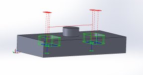
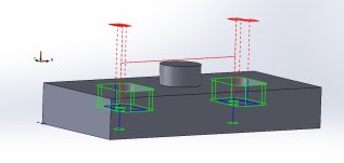
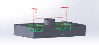
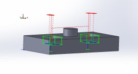
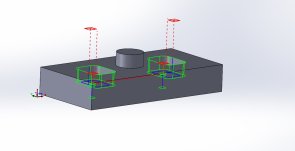
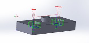
Here's 4 screen shots of the exact same part, using my default settings but moving my WCS. As you can, my tool paths never changes and each path clears the part. These are my default settings, so no you do not "really need to set every retract and clearance plane properly every single time"

If you understand how NC clearance planes work, you can throw your WCS out into law law land anywhere and your tool paths clearances will never change.
 

Attachments

  • Bottom Stock.jpg
    Bottom Stock.jpg
    74.7 KB · Views: 8
  • Top.jpg
    Top.jpg
    70.9 KB · Views: 8
  • Z DOWN.jpg
    Z DOWN.jpg
    57.8 KB · Views: 7
  • Z UP.jpg
    Z UP.jpg
    61.9 KB · Views: 8
I prefer to set Z zero on top of the part. If there is some to be faced off then thats positive, and everything below top of part is negative. Most times anyway.

Setting Z zero on bottom can be easier to crash. You really need to set every retract and clearance plane properly every single time, and they will always be different numbers based on size of part. If its on top you can use the same values for clearance most of the time. And this is handy because you can setup operation defaults to save time.
Here's the same tool paths but using NC planes based on where the WCS is placed. Moving the WCS to the bottom of the stock just doesn't work, and moving it to the top the feed planes are dumb. With some skim plane configuring its an easy fix, and works, but I don't like the idea that my tool paths could change based on where my WCS is placed, I configure my NC planes based on the part and/or stock to ensure proper clearance no matter where my WCS is placed on a part.
 

Attachments

  • Bottom WCS Origin.jpg
    Bottom WCS Origin.jpg
    67.1 KB · Views: 1
  • Set Up Origin PLANE.jpg
    Set Up Origin PLANE.jpg
    65.6 KB · Views: 1
Meh, you are correct. CAM does take care of the proper clearance and plunge planes, but can we at least agree that if Z0 is set at the top of the part, it is easier and more obvious to read the rapid moves to make sure they do in fact clear?
If you have a clamp for example that is borderline at your rapid plane. Just slap a 1" block on top of your Z0 and eyeball it to be sure.

As far as where to set Z, I go both ways as I see fit, so no argument from me.
I guess if you are stepping through a part verifying every single rapid move plane, sure. I rarely watch my code anymore, occasionally I will verify with an NC editor's back plotter, I'll take a quick glance and make sure nothing looks funny. But I have parts that have 8 hour cycles across 25+ tools, I am not stepping through a program like that. Once that tool comes down to its G43 H - height offset line which I typically have set to Z1.00" above the stock, I trust my post is configured correctly to match my CAM simulation. It's been years since I have been burned.

CAMWorks also post's out a set up file along with the NC PGM and within the tool list it shows a Z MIN/MAX value, and having my WCS at the bottom of the part, with a quick glance, I know my tools aren't going to bury themselves into the table cause unless it's a hole operation (drill, tap, reamer) chances are there won't be any -Z values. And of course I always know my stock size so my +Z values will always be larger than my stock size, so if I noticed one was not, I would know there's a rapid plane issue.
 
In the CAD/CAM just pick the most appropriate feature and be consistent.

On 3 axis verticals when setting tool and work offsets there are methods that are better than others. With 2 machines that take the same 40 taper tooling you should consider having an offline tool setter. With an offline setter you can move the tools between machines, don’t waste table space or time measuring tools, and all the tools work with any work coordinate.

This means you need to use negative work offsets and positive tool offsets on the CNC controller. None of this affects your CNC programming and how you choose to do that…. It only affects the numbers in the cnc controller
I use an offline tool setter and my tool offsets are negative values and typically my machine Z work offsets are positive values. My vise bed is Z0 in my machines based on how my tool setter is set configured.
 
I prefer to set Z zero on top of the part. If there is some to be faced off then thats positive, and everything below top of part is negative. Most times anyway.

Setting Z zero on bottom can be easier to crash. You really need to set every retract and clearance plane properly every single time, and they will always be different numbers based on size of part. If its on top you can use the same values for clearance most of the time. And this is handy because you can setup operation defaults to save time.
Here's more, as I said earlier I move parts from my verticals to my horizontal occasionally as well and the machines offset is bottom center of the tombstone.

So if I bring this part in to my tombstone and the coordinate system is based on the part and/or stock, the toolpaths still don't change with the WCS being where it is at.

Now if the planes have anything to do with the WCS placement, you can see what happens.

It comes down to understanding how the NC planes function and picking the correct settings based on how you set your parts up. The WCS placement should be irrelevant for safest programming, IMO.
 

Attachments

  • Untitled.jpg
    Untitled.jpg
    100.7 KB · Views: 5
  • Set Up Origin Tombstone.jpg
    Set Up Origin Tombstone.jpg
    129.2 KB · Views: 5
i'm a big fan of a subplate system and a set work offset with workholding that always goes back to a known, repeatable position. most of the stuff i do, my g54 is on the subplate, and i place whatever i'm machining in whatever workholding i'm gonna use both in cam and in machine. i hate indicating and probing shit.

^^^ I would love to put together something like this one of these days.

--------------------
Most of the stuff I do is vise work or a small sacrificial tooling plate.

I set X & Y wherever is convenient - usually, it's X against the hard jaw and Y on the centerline of the material because that is how I like to program.

I usually set Z from the top of the parallels / bottom side of the material. I don't like setting Z off of material that gets machined away.

Setting Z from the bottom of the part will also ensure that you will always have the correct amount of stock for the next operations.

For example; you program a part for 2" x 3" cubes of material. 6 months later, you can't find 2 x 3 but you can get 2 x 3.25. When you set up for OP1, just add a few more facing passes and you're done, nothing else has to change.
all my vises have dowel pins and are located precisely on subplates, so as long as i place the stock for example lined up with the edge of the vise, i'm GTG and no need to probe anything. the only thing i'd ever remotely probe/indicate is 2nd op stuff thats SUPER critical. otherwise i can usually line up 2nd up within about .001"
 
otherwise i can usually line up 2nd up within about .001"
Just by lining it up with the edge of the jaw? That's pretty darn good!

I'm trying to picture how this is set up; I'm assuming you have something like a 1" counter bore in the sub plate for setting X & Y? Set the sub plate on, indicate the front edge straight, sweep the hole to set G54.

From there, you have various fixtures that pin/bolt to the sub plate in a known location. All programs use the original sub plate G54 location and in CAM, you move the part origin over to your known fixture location. Is that right?

The programming aspect is the part I'm unsure about. How do you put the part where it needs to go in CAM and how do you keep track of the various fixtures locations?
123 block my friend!
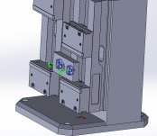
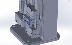
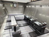
here's an example: this is FCS fixturing, but the principle is the same. precision bores/holes on a pattern. i have this modeled in my CAM template, any time i start a new program, the cad model of the machine and fixturing is already there, i place the model where i want it, make sure my vises are in the same spot on the machine as in CAM - and voila, full send.
in this example, my work offset is the top of the left/bottom bore on the left beam. and i havent had to change it yet.
1692668857667.png
 
Last edited:


Back
Top