What's new
What's new

Cincinnati mill: Rage + a question

westcoastr

Plastic
Joined
Aug 6, 2021
Location
Bay Area
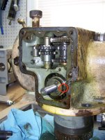
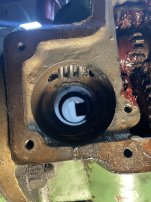
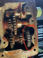
So I finally got around to pulling the side plate off of my mill head (Cincy 1-B Toolmaster) and look what I found in the “oil” system…enough grease to win WWII. Anyways…

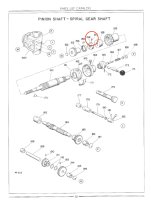
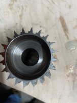
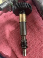
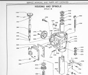
Anyone know how to get the male friction hub and spiral gear circled in red off of the quill shaft? The book makes it seem like they just pull off, but there is nothing to grab on to and hammering the shaft to the right doesn’t seem a good idea.


IMG_4131.jpeg
 
It's been awhile since I had the head apart on my 1954 Toolmaster 1-B, but I don't recall having to use a puller to remove the clutch adjusting collar. From the photos I made at the time (see below) and service manual M-1890 (dated 1956), the clutch looks like it is held to the shaft with a set screw (circled in red in the photo).
 

Attachments

  • 100_1214.jpeg
    100_1214.jpeg
    467.5 KB · Views: 47
  • Screenshot 2024-01-22 at 8.49.09 PM.jpg
    Screenshot 2024-01-22 at 8.49.09 PM.jpg
    547.7 KB · Views: 47
It's been awhile since I had the head apart on my 1954 Toolmaster 1-B, but I don't recall having to use a puller to remove the clutch adjusting collar. From the photos I made at the time (see below) and service manual M-1890 (dated 1956), the clutch looks like it is held to the shaft with a set screw (circled in red in the photo).
Elwood, thx. yes I removed the collar with set screw already. I finally finessed the clutch and spiral gear out this morning and found out the spiral gear had massive wear on it, the teeth were ground into sharp knives basically by the grease/debris and was also causing it to stick. All good now, just need to figure out how to make a new spiral gear (and probably the worm gear it was meshed with with) and get a clutch friction surface on it...back to the rabbit hole. Also pretty wild that the manual calls to drill out freeze plugs in the head casting to access the other gearing. Weird there is no easy access and why does a non sealed casting need freeze plugs? The fun continues! Not looking forward to taking the spindle/quill apart - no problems in the spindle and normally I'd leave it alone until it fails, but with this metal shaving/grease mixture everywhere in the machine I need to check it out.

So weird this machine has some parts totally wrecked and others look like they just came off the assembly line.
 

Attachments

  • clutch auto downfeed spiral gear.jpg
    clutch auto downfeed spiral gear.jpg
    2.8 MB · Views: 33
Ouch. Surprising the amount of wear on that gear. I recall that it turns whenever the spindle is turning, but that's a lot of metal gone. I don't see that any of the other visible gears in your photo show wear like that.

As to the "freeze plugs", I'm not sure what you mean by "non-sealed"? The head casting should have oil in it.

Be sure to also check the phenolic gear, on top of the vertical driven shaft, under the motor housing. Mine had split on the pin:

100_1219.jpeg
 
Ouch. Surprising the amount of wear on that gear. I recall that it turns whenever the spindle is turning, but that's a lot of metal gone. I don't see that any of the other visible gears in your photo show wear like that.

As to the "freeze plugs", I'm not sure what you mean by "non-sealed"? The head casting should have oil in it.

Be sure to also check the phenolic gear, on top of the vertical driven shaft, under the motor housing. Mine had split on the pin:

View attachment 424476
Yes sorry they call them "expansion plugs" but same idea. There are enough holes in the head that even if you filled it with water and froze it, it still wouldn't build pressure and crack the casting. And just weird you have to drill something out to access it and then have to McGyver up some fix to get it back in and working.

I can only guess that by packing the head with grease instead of oil, it caught some metal filings and formed a glob of gear grinding goop in that spot.

My phenolic looks like they made it yesterday as do many of the other gears.

I think my best option is to flush the head as is in mineral spirits, put it back together and be careful when I use the power downfeed. Just need to disassemble the spindle to check it for issues.
 

Attachments

  • Screenshot 2024-01-24 062204.jpg
    Screenshot 2024-01-24 062204.jpg
    102.4 KB · Views: 5
On the X-axis powerfeed gearbox of these Toolmasters, the factory inserted brass plugs instead of expansion discs. Same procedure, though: drill, tap, and pull. But then one has to make new brass plugs. At least the expansion plugs can be bought off the shelf.

Have you pulled the mating pinion shaft? I'm curious to see what the worm looks like.
 
Concerning freeze plugs this just one of the generic names for slightly domed disks that you drop into a hole until it abuts the flange at the bottom then bonk with hammer, via a drift slightly smaller than the plug, to flatten it so expanding it into the hole. In the UK we tend to call them core plugs as such holes were generally provided to help remove casting sand from hollow sections. Back in the day such disks were readily available in a host of standard sizes from motor factors and engineering suppliers.

Simple and effective way of sealing holes that might only have to be opened once or twice in a machines life, if at all. Way cheaper and easier than threading for a plug or providing a cover held by several bolts.

Clive

PS Elwood keyboards faster than I.
 
On the X-axis powerfeed gearbox of these Toolmasters, the factory inserted brass plugs instead of expansion discs. Same procedure, though: drill, tap, and pull. But then one has to make new brass plugs. At least the expansion plugs can be bought off the shelf.

Have you pulled the mating pinion shaft? I'm curious to see what the worm looks like.
The worm that the clutch gear mates to seems perfectly fine - see pic. All the others seems fine expect the one gear circled, it has some sharp edges/wear but pretty minimal - it mates with the worm on the shaft with the phenolic gear-which also look fine. Maybe the worms were make with harder steel, dunno but so far only gears that mate with a worm have any kind of wear.

The phenolic gear/shaft look nearly new.

I don’t think I’ll drill those plugs and disassemble the remaining at this time. I need to use the mill soon.
 

Attachments

  • IMG_4142.jpeg
    IMG_4142.jpeg
    2 MB · Views: 18
  • IMG_4143.jpeg
    IMG_4143.jpeg
    1 MB · Views: 17
  • IMG_4144.jpeg
    IMG_4144.jpeg
    2.1 MB · Views: 17
Concerning freeze plugs this just one of the generic names for slightly domed disks that you drop into a hole until it abuts the flange at the bottom then bonk with hammer, via a drift slightly smaller than the plug, to flatten it so expanding it into the hole. In the UK we tend to call them core plugs as such holes were generally provided to help remove casting sand from hollow sections. Back in the day such disks were readily available in a host of standard sizes from motor factors and engineering suppliers.

Simple and effective way of sealing holes that might only have to be opened once or twice in a machines life, if at all. Way cheaper and easier than threading for a plug or providing a cover held by several bolts.

Clive

PS Elwood keyboards faster than I.
Ahhh so that makes a lot of sense. Budget trolls always win in the end.
 
They are called core plugs because the core has to print out into the drag (usually). Print out means the core is locked into the outer mold. To do so, the core must protrude through the wall of the casting. It appears the big opening in your gearbox would have been plenty large enough to remove the core sand, but it wouldn't have provided enough area to provide a firm lock on the core when the molten iron was introduced.
 
They are called core plugs because the core has to print out into the drag (usually). Print out means the core is locked into the outer mold. To do so, the core must protrude through the wall of the casting. It appears the big opening in your gearbox would have been plenty large enough to remove the core sand, but it wouldn't have provided enough area to provide a firm lock on the core when the molten iron was introduced.
Casting, I feel, is more black magic than science lol.
 
OK so I have completely disassembled my Toolmaster head except for the spindle (need to make a spanner) and the quill depth stop. Does anyone know how to get the quill stop apart? I've removed the pin (165B) but the shaft (160B) is still captured. Do you pound the shaft out from the bottom? Is it just a press fit on 167B? Parts 164B and 166B spin freely. I tried some medium whacks and it seems like I am hitting something that doesn't want to move.
 

Attachments

  • Toolmaster head parts drawing.jpg
    Toolmaster head parts drawing.jpg
    621 KB · Views: 8
Holy heck, you have to heat and whack the quill depth stop shaft like you are tenderizing abalone - steel on steel super tight interference fit on part 167B. How I didn't crack the casting is a miracle.


Back
Top