What's new
What's new

Fadal Pendant Wiring

Duc

Aluminum
Joined
Aug 20, 2013
Location
ABQ, NM
Does anyone have a wiring diagram of the flexible cable that goes to the Fadal MPG Pendant? I forgot to pin out the cable before I removed all the wires from the amphenol 22-14S connector before switching to a new cable. The fadal drawings show the Amphenol connector pinout but is missing the J1 molex connector inside the pendant.

Removed picture since it was wrong.
 
Last edited:
If you go on itscnc website click on resources, wiring diagrams and there you can find the pinout.
Found a troubleshooting drawing in my paper manuals that I have not seen online that somewhat shows the pinout. The fadal drawings are general lacking on the pinout for interface cables. I have spent some time pinning out the setup and referencing documentation for the chips built onto the boards. Would have been faster if I didnt misread the second chip number on Friday.

1. MC3487N Chip inside the Hand-held: used to boast the signal for the MPG.
2. SN74148N Chip inside the monitor cabinet. Converts from 6 inputs into 3 outputs for the system.

The info on the drawings has yet to be varified till my new cable comes in. I did have to guess on the input to the 74148 chip set but I do have a warn out cable coming from a buddy that I can pinout before building him a new one.

Once finished someone could make a new board to interface other units into a fadal machine.


Edit: Cable pinout has been tested. Uploaded a new picture
Hand-Held pinout Rev 2.JPG
 
Last edited:
The pinout for the WIR-0538 :REPLACEMENT CABLE,MOLDED;REMOTE MPG

J1 connector to amphenol 22-14S
1 -> J (Y-Axis)
2 -> K (Z-axis)
3 -> H (X-axis)
4 -> L (A-axis)
5 -> E (Tool release)
6 -> M (B-axis)
7 -> F (Tool Release)
8 -> N (C-axis)
9 -> C (MPG B)
10 -> B (+5V)
11 -> D (MPG A)
12 -> A,T,G (Grounds)
13 -> S (.0001)
14 -> A,T,G (Grounds)
15 -> R (.001)
16 -> P (.01)


I have some new connectors and a 19 pin coiled connector coming from ebay. The total was about 50 bucks for both.
 
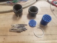
Connector comes apart. More a interesting fact than anything
connector disassembly.jpg

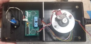
New wire inside pendant
Pendant inside.jpg

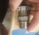
Turns out a Electrical clamp fits inside the backend of the connector. JBwelded the connector inside the backshell to provide strain relieve. Past setup the backshell was filled with plastic. Painted the electrical connector black to look a little better.
20220709_191814.jpg
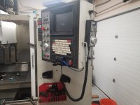
$40 dollars later. A working pendant
pendant on mill.jpg
 
That's great. I have a Fadal MPG with no cable, however I'm missing the proper connection on the bottom of the pendant. Is the Binary > Octal encoder on the little board inside the main pendant. I believe on a factory system that board is soldered to the AMP connector then the ribbon cables go up to the Pendant boards.
 
That's great. I have a Fadal MPG with no cable, however I'm missing the proper connection on the bottom of the pendant. Is the Binary > Octal encoder on the little board inside the main pendant. I believe on a factory system that board is soldered to the AMP connector then the ribbon cables go up to the Pendant boards.
Can you take a picture of the area that you are referring to?


Back
Top