Milland
Diamond
- Joined
- Jul 6, 2006
- Location
- Hillsboro, New Hampshire
Mithril's no use for home applications, too many orcs about. The glow would keep you up all night.
Follow along with the video below to see how to install our site as a web app on your home screen.
Note: This feature may not be available in some browsers.
Are you suggesting I have a frame custom cast? Because I'd love that, but the idea is to build this out of reasonably accessible components, and even a small (2-4 kilo) casting here in Japan would be thousands of dollars before the machining that would be required to make it even useful. Maybe I misunderstand what you are suggesting, it isn't really clear.
As far as bolting things to big hunks of metal, my base plate that this will be built onto, and form the basic bed is a 72KG cast Iron Surface Plate that had been abused over what I can only assume is the last 50-60 years. It took days of hard work getting the layers of congealed dirt and corrosion off of it, I'm pretty sure it had been buried in the dirt for a while at some point, but the ancient layers of grease and quality iron kept it in recoverable shape. It was primed and then painted with several coats of 2-part epoxy machine paint.
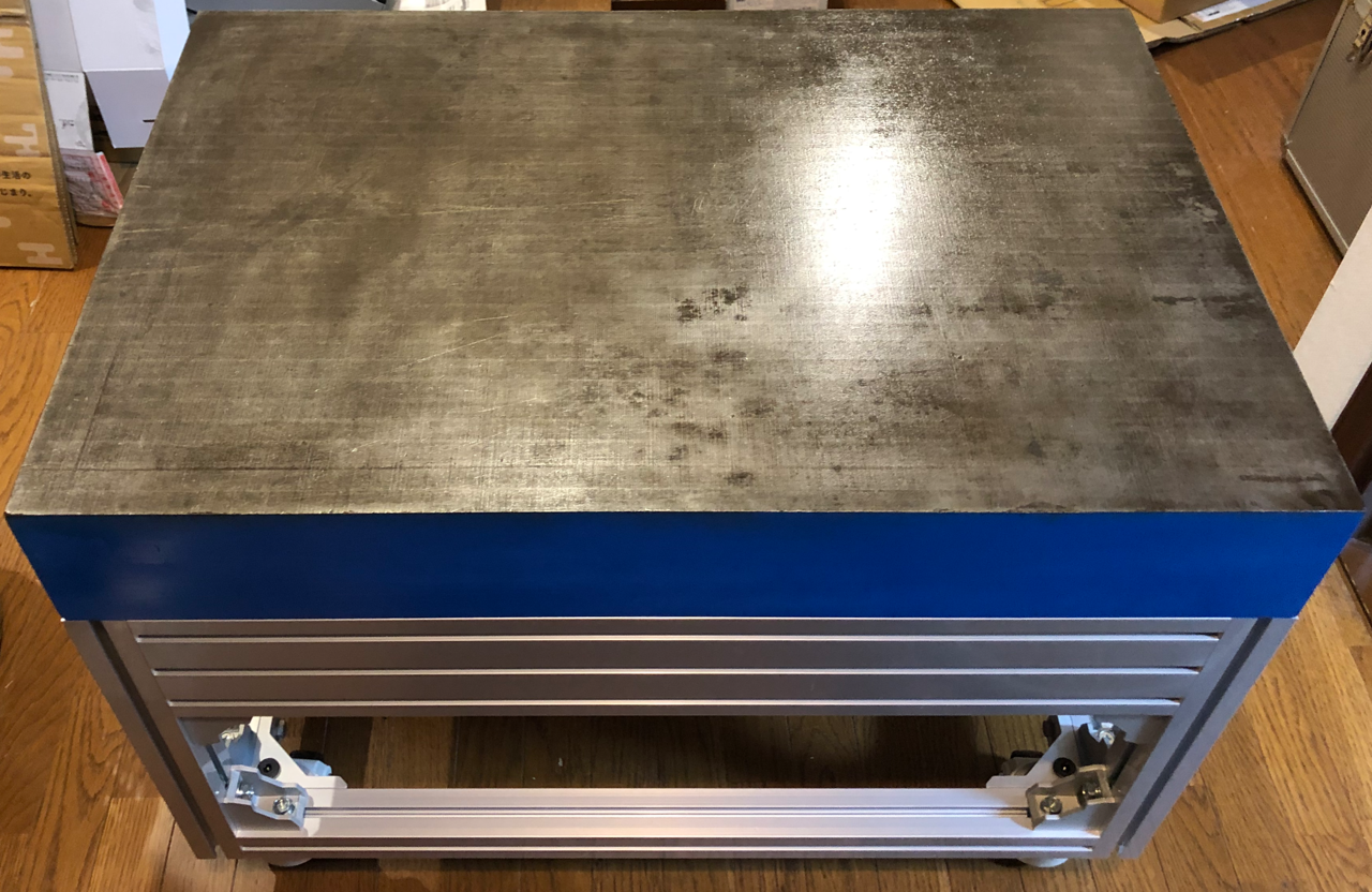
It is bolted to a stiff aluminum undercarriage and machine casters to help move it around, the total weight will be close to 300 kilograms when complete. It will ultimately be tethered to reinforced mounting points on the floor. Neat fact! I have heard recently that some people with an unfortunate overabundance of fecal production require specialized toilets that actually exceed the total weight of this machine!
The main structural members of my design are going to be the much derided Aluminum extrusions. They are however much larger and stronger than typical, made with JIS A6N01S-T5 alloy and 100x200mm M10 profile. Are there stronger materials I could be using? Yes, and they are not secrets, even a section of mild steel square tubing would likely be stiffer. But there are tradeoffs to be considered, and one of the biggest is the material processing requirements. There are also weight, cost and recyclability factors I outlined above. The extrusions are turn-key, drop shipped to my door perfectly sized, and have a multitude of mounting opportunities without any post processing required.
The fact is that there is a certain amount of 'bootstrapping' that is made available by building it this way. Whatever the capabilities of the Al turn out to be, it is highly probable that it will be enough to build its own reinforcements. Incrementally targeting weaknesses that are identified. Potentially being able to properly machine the surfaces and attachment points onto steel plates or even, if it turns out to be necessary, a replacement steel gantry tube.
So I respect the thinking, and I understand the wisdom of copying what's come before, but please realize that I have a very different set of constraints (not all of which are easy to get, although I'll continue to do my best to explain them) and have zero intention of doing any kind of radical design change at this point. Short of being presented with some persuasive evidence that it will not work, the layout you see is the layout it will be. These parts are sitting next to me, I'm just sharing what's happening.
This is built at home....so is home built....
Epoxy granite cnc mill walk around - YouTube
Yes, I am suggesting starting with a solid cast iron frame. Just having a solid base as you have proposed doesn't do it, IMHO. What you want is a super stiff frame.
Every hobby type project of this type I've seen always compromises the design right up front by using aluminum for the frame and then the whole project is compromised.
I do understand that you have constraints, money and otherwise, BUT maybe if you were to make just one investment in the project it would be to get the frame super stiff.
If I were doing such a project, I would look at all the professional CNC machines out there and understand how they designed their frames and then scale down in size. As mentioned, my brother speedio CNC has a LOT of metal, all one piece, that makes up the frame of the machine. Anything that moves leverages off that big chunk of metal. It is not built out of aluminum struts that flex.
This is built at home....so is home built....
Epoxy granite cnc mill walk around - YouTube
")
Also LOL at the linear motor suggestion. That will double the cost of this project, if OP is lucky, and he'd get to take advantage of approximately zero of the potential benefits in this application.
Also LOL at you. I know people selling them and making them. They are widely used in chip automation and pick-and-place robots already and they even built a little demo machine for testing switches, which was fun to watch. They have some nice rotary tables, very competitive with conventional systems (except they perform better).Also LOL at the linear motor suggestion. That will double the cost of this project, if OP is lucky, and he'd get to take advantage of approximately zero of the potential benefits in this application.
This is built at home....so is home built....
Epoxy granite cnc mill walk around - YouTube
Does look nice. Table looked a little skimpy under the t-slots but that probably won't matter for his use. Maybe he'll even need a chip conveyorThis is exactly the kind of machine I was suggesting, great video, and smart guy. ALL hobby CNC prospective builders should review this video....

Ignoring the predictable and pointless drama, here's my 5-minute take as a fellow engineer:
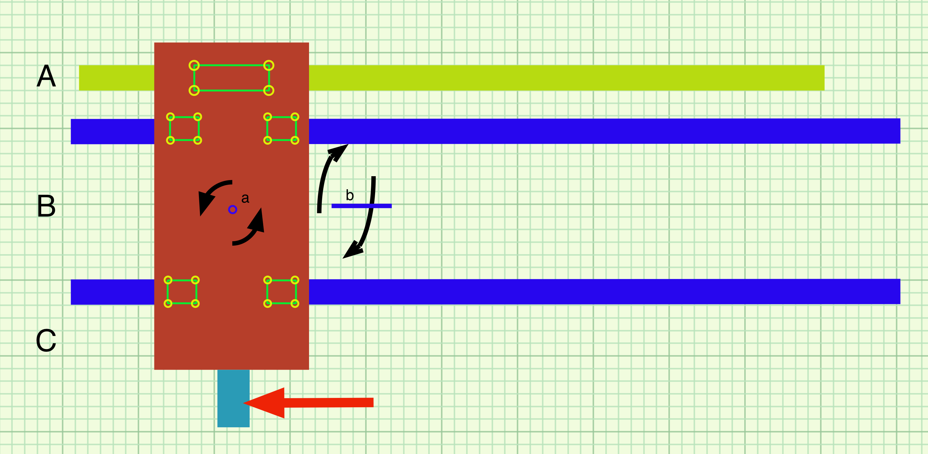
I agree with the suggestion to center the X-axis ballscrew between the rails. It's not so much a question of whether the rails can "handle it" - they can - it's more a question of machine deflection. More is more, and less is always better. The force on the tool + the counter-acting force of the ballscrew create a torque couple which will be greater with the ballscrew positioned as it is in your OP.
On the topic of servos vs. steppers, I don't necessarily see any issue with the stepper you've chosen. Oriental Motors are solid products. Is a servo better? Yes, but tend to be much more expensive. If ever you do want to move to servos, I have three suggestions that might work for your situation:
1. Check auctions. Chances are it will take quite a while for something suitable to come up, so I wouldn't hold up the machine construction on that account. Along with servos you'd need a single-phase servo drive. Which do exist but are relatively rare on the auction circuit. I've picked up about 10 servo motors this way. Including 3x brand new Kollmorgen servos, for $100/ea, which retail for about $1500~$2000. Getting matching single-phase drives will be difficult, but possible. And they don't necessarily have to match. It's a pain in the ass option, especially including the shipping to Tokyo and the extra cost to have someone pack and ship them...but it's possible!
2. That aside, check out Teknik's Clearpath integrated servos. They are real servos and run off of 75VDC. They won't be as high performing or reliable as "true" 480V 3-phase industrial servos, but they're solid devices. Assume $300~$600 per servo (which includes an integrated drive). They also have models that are drop-in replacements for steppers, and will accept the same step/direction signals. In other words you can keep the exact same control system.
3. I've not used them, but a few months ago I came across an affordable servo system that was higher performance than the Clearpaths. They are real servos and drives, not weird homebrew/DIY stuff. I thought I had it bookmarked but apparently not, and the name escapes me. I'll keep looking and post here if I track them down. The gist is that you can kit out a 3-axis CNC system for a few thousand bucks. That includes all servos, drives, and IIRC a motion controller. Add the cost of one motor since you're dual-driving an axis.
That aside, I will whole-heartedly endorse whidbey's note on stiffness. A 2.5" aluminum plate with 90% of the material removed will be stiffer than a 1" thick solid steel plate. It will also weigh a fraction as much. This really only matters if you have the freedom to choose either larger extrusions, or have a custom part machined. No idea what that's like in Tokyo but it sounds like it's not easy. Of course you could always have someone here mill it for you and ship it as "scrap metal."
Focusing in on the rails themselves, a few things to note. Maybe you already know this, but lots of engineers don't:
1. Pay close attention to the preload of the bearings. There are varying levels of preload including "clearance" or "no preload." You don't want either of those. The OEM's datasheet or catalog will tell you which is which and what options are available. Any particular bearing size from an OEM is usually offered in a number of preload configurations. Don't assume on that front...confirm with the OEM. Higher preload = stiffer bearings. A big bearing with no/low preload may be less stiff than a smaller bearing with high preload. Yes, the bigger one will be stiffer after you take up all the slop and initial deflection, but by that time things have already moved quite a bit. The downside of higher preload is increased rolling resistance. Another downside is that as bearing preload goes up, the tolerance to system misalignment goes down. Which brings me to...
2. Have a plan for aligning bearings. Not only aligning the axes relative to one another, but aligning the rails to one another. The "move it back and forth while tightening and checking for resistance" kinda-sorta works, but doing it with an accurate indicator is even better. It's common to have a clean reference surface to precisely locate one rail, and then indicate the other one in. There are all kinds of methods you can Google if you've not done it before. The key takeaway is that even very tiny misalignments (i.e. rails not parallel) can generate enormous forces within the bearing blocks. Which you might not notice, until they literally explode. I've seen it happen. The stiffer your bearings and system, the more attention you need to pay to this. Which brings me to...
3. Think about ensuring you are not overconstraining the system. If you have two very stiff bearings, and a very stiff carriage between them, you risk overconstraining the system. Whether due to operating forces, or mismatched amounts of thermal expansion (e.g. your spindle carriage vs. the machine base), or whatever - the result will be much higher loads within the bearings than intended which can cause binding and/or premature failure. To prevent this, usually there is some compliance required somewhere in the system. This can mean a number of things. It could mean running one bearing with a high preload and the opposing bearing with light preload. It could mean compliant structures that are stiff in one direction and compliant in the other (e.g. for your Y axis, it would be stiff in the Y axis and compliant in the X-axis). Servo couplings are a great example of this.
It could also mean just having a sufficiently compliant carriage between the bearings that it's not a huge concern because it isn't capable of generating high enough forces to cause issues for the bearings. The key point is one that is often lost on engineers and laypeople alike: "stiffness" isn't a material property, it's a structural property. Choosing stiff bearings in isolation won't mean much, nor will choosing a stiff machine structure with sloppy bearings. Gotta look at the whole thing as a system. My gut feeling is that the extrusion will be sufficiently "soft" that they provide the necessary compliance. Something to think about.
4. Roller bearings are better than ball bearings. But pricier.
5. If you can, I would strongly consider spreading apart bearing blocks (which share a rail) as much as practical. I definitely see some opportunity there in your Y-axis. It will reduce the impact of any "give" in the bearings, and may lower the forces that the bearings see in use. It will also help prevent binding, but that's not a top concern here IMHO. It may increase the machine footprint slightly (or reduce the work envelope) but if you can do it, it'd be a plus.
That's all I got for now. Good luck! Definitely interested to see how this goes. Here's another home-brew epoxy-granite mill that definitely goes above and beyond the usual maker-fare.
Also LOL at the linear motor suggestion. That will double the cost of this project, if OP is lucky, and he'd get to take advantage of approximately zero of the potential benefits in this application.
Also LOL at you. I know people selling them and making them. They are widely used in chip automation and pick-and-place robots already and they even built a little demo machine for testing switches, which was fun to watch. They have some nice rotary tables, very competitive with conventional systems (except they perform better).
One again, you do not have an arfing clue. About a year ago we spent several full days visiting a company making these things. Not just the motors, the drives and the controls AND complete machines of several varieties. Also direct drive rotary tables, and a bunch of other stuff. Mitsubishi thought enough of them to drop a 10% stake into the company. If I were younger I'd be peddling their machine tools, they are pretty nice, but they actually have bigger plans.Pretty sure I never questioned their utility or existence. They are way more expensive, tend to be considerably more bespoke than bolting on a rotary servo, and require scales and more sophisticated drives. Meaning more $$$. A lot more.
I'm happy to be wrong if you can think of a tangible benefit for OP from switching to linear motors, and/or if he can outfit 3 axes with linear motors for less than $5k - which will buy you a very nice servo system. Otherwise sure they're neat but they're a pointless expense and a whole lot of additional hassle to boot.
There I go again.
Sometimes an idea becomes a "signature", rather than a practicality. EG signs his name "Linear Motor".
About the op, I'm far beyond caring what the hell he does, it's just another C N C Zone thing. Not interesting.
")
The lever arm is much shorter, I calculated roughly an increase of 30-40% over the actual load seen by the cutting tool, but clearly not helping.
@Baka, sounds like you've thought about most of this and you're on a good path. Like most such machines I wouldn't expect miracles in the rigidity department, but hell...people cut steel with Shapeokos and you should be well ahead of that barring any major screwups.
As far as the bearing preloads, this usually comes from the bearing block, so if ever needed (or you just have nothing better to do) you can always order new ones with increased preload. Would be an interesting A/B test running the same part/tool/program. You won't be taking heavy cuts with this machine so the benefit is questionable. At some point either have to simulate it, or trial it, to get an idea of the benefit (if any). Guidelines only go so far.
Steppers vs. servos, again depends if you'll notice/care about the difference. Especially closed-loop steppers with encoders. Servos have a higher power density and better dynamics. Does that matter for you? Probably not - and by the time it does you can easily upgrade.
For the diagram, not sure I agree with some of your assumptions.
- The ballscrew is tasked with resisting the cutting forces regardless of where it is. I wouldn't expect to see any difference in loading on the screw (and resultant motor torque) between any of these positions. The whole point of the rails, after all, is to carry all of the loads except those parallel to the rail.
- Even with a ballscrew centered between the rails you'd still have some torque created, just a bit less. In all cases, regardless of ballscrew position, the bearings will barely notice this torque. It only matters in that it will technically reduce the deflection. Will that reduction even be noticeable? Impossible to say without a deeper dive and testing/sims. This will be easiest to test with a dial indicator once it's assembled, but of course that's the hardest time to make changes.
- In consideration of the above I agree it's not ideal to push the spindle away from the X-axis rails for the sake of fitting a ballscrew. I was thinking more to make it fit "inside" the extrusion (cut a trench or some such). But eh. You can accomplish more by just popping in some stiffer bearings someday.
- The weakest point of builds like this, IMHO, is the aluminum extrusion. Unfortunately the hardest to replace. All of the motion components are off-the-shelf, but for the actual frame you'd need to either get lucky/DIY or get something custom. Maybe for another day.
- On the metrology gear, as long as you have what you need to attach a dial indicator to one bearing block and use it to sweep the entire length of the opposite rail, you should be good to go. With a system like this and light preloads...you honestly might be fine just doing the "roll it back and forth and tighten the rails incrementally" method. But actual measurements make this easier so use it if you got it.
- Do your bearing blocks include scrapers, or just rubber seals? Rubber seals work great in general but they're not really intended to remove large chunks and bits of metal. They may get chewed up in a hurry if your rails aren't covered. Eventually, provided you maintain them, they will start pissing grease everywhere as it accumulates, and things like to stick to that grease. This is easy to solve with waycovers and also a quick wipe with a rag now and then. Just don't expect the bearing seals to last toooo long if they're tasked with scraping chips off the rails.
Can you elaborate on this a bit? Not entirely sure what you mean.
If you can find a bearing ball supplier who stocks micron +/- on either side of common diameter (3mm, 3/32", etc.), you may be able to reball your linear trucks, as well as the ball screw. But that's a bit of a challenge if you can't measure the balls correctly or repeatedly. And of course, the right size is always the one not stocked...
I think it's pretty clear that you need a properly supported known-straight reference to get the rails installed correctly. Just sweeping one rail to the other can give you a parallel squiggle, not ideal for precision machining.
The two Y Al extrusions will have to be packed to be any use, even with just a lightly bonded sand (mixed with a weak glue, like Elmer's?). Otherwise they're just two flexures in X. A water-based glue might change with evaporation, but would be easiest to use and dispose of afterwards (just break up the clumps, nothing hazardous in the mix). Plan on installing endcaps at the least.
some might think I have a hoarding problem... they wouldn't be wrong.
Notice
This website or its third-party tools process personal data (e.g. browsing data or IP addresses) and use cookies or other identifiers, which are necessary for its functioning and required to achieve the purposes illustrated in the cookie policy. To learn more, please refer to the cookie policy. In case of sale of your personal information, you may opt out by sending us an email via our Contact Us page. To find out more about the categories of personal information collected and the purposes for which such information will be used, please refer to our privacy policy. You accept the use of cookies or other identifiers by closing or dismissing this notice, by scrolling this page, by clicking a link or button or by continuing to browse otherwise.