What's new
What's new

MV-35 Troubleshooting

It's a board, jancd-cp01 to be exact. Unusual board construction to me, It looks like armature wire embedded in a gel coat for traces, and a lot of it, both sides. There's no shortage of real estate on this thing.
A 0.01 cap got hot around the lead in the through hole. Oddly a wire trace is damaged and broken in 2 places either side of the cap, trace doesn't look burnt and it doesn't junction with the cap. I suppose it could be just the weakest link in a cascading failure.
 
Jancd-cp01 board wasn't the problem. The capacitor was a previous failure that was fixed with jumpers on the bottom of the board.
. I've looked over all the boards .. Nothing obvious
Sure wish I knew how the original poster fixed his problem..
 
Still working on solving my problems. Just ordered cp01 board,(2) 10O1b boards and a servo power supply, jznc-tu04.
Have a request into yaskawa for information and applied for credit with dmg mori so that I can talk with tech support.
 
I did figure out my power up problem. Somehow I managed to wipe all the parameters from the control without having the controls set to write parameters. I did a memory regeneration and it fired up with X,Y,Z servo errors. They cleared once I got all the parameters back in it. Luckily one of the first things I did when I got the machine was take pictures of all the parameter settings.
Now I can't get the machine to zero return, when I try it goes past zero and stops at a over travel switch. Nor get the automatic tool changer to cycle. Maybe I screwed up something digging around in it trying to fix it.
At least now I have a half dozen different, good used boards .. I bought them right before I did the memory regeneration.
 
I know this is an old thread. Our JANCD-CP07 board developed a short which we were able to troubleshoot. The issue was fixed by replacing the burnt serial port line driver SN75188, but in the process of fixing the boards, the battery was removed from the board that contains the memory/parameters.

We did a parameter backup prior to losing everything. We input all the parameters per what we downloaded but we're still getting 310: SERVO OFF alarm.

Did you ever resolve your issue? I know the OP never followed up. I don't like bringing threads back from the dead but maybe we could help each other or some other poor soul in the future? (maybe those souls could even be us?)
We also have SVM contactor that is not latching, and I'm not able to figure out how the signal reaches the contactor to latch it to send power to the servo's. The contactor works, and powers everything up if we manually actuate it, but I really don't like doing that out of sequence because I don't have a complete understanding of the logic involved. I also don't want to cause more issues.

Do you, or does anyone else, have a signal flow diagram or some sort of schematic for how the signal is sent to the SVM contactor?

forgot to add this is a Yasnac MX2 on a Mori Seiki MV35/40
 
Last edited:
I'm away from my notes right now so I don't know exactly what's going on but I think it's just a matter of getting everything re-initialized .. Possibly still a parameter problem .. Did you get the hidden parameters back in there also?
 
"hidden"

Perhaps I did not!
Are those in the 6000 range with no way to change them while modifying the rest of the parameters?

I'm not at the shop and probably won't be able to get there for a couple days. No hurry. I appreciate the response!

- Travis
 
"hidden"

Perhaps I did not!
Are those in the 6000 range with no way to change them while modifying the rest of the parameters?

I'm not at the shop and probably won't be able to get there for a couple days. No hurry. I appreciate the response!

- Travis
I believe those are the ones .. You have to point the rotary switch in position 4I think .. The one in by the tape reader
 
I believe those are the ones .. You have to point the rotary switch in position 4I think .. The one in by the tape reader
I'll give the position 4 on the rotary switch, the one inside the tape reader compartment, a try just as soon as I can. Thanks for the info. I definitely did not see that anywhere in the manuals.
I will document the results and report back.
 
I believe those are the ones .. You have to point the rotary switch in position 4I think .. The one in by the tape reader
Moved rotary switch to position 4, in the Tape drive cabinet.
powered machine on
pressed green button on NC to turn NC on
pressed PRM
modified 6219 0 to 6219 1
now parameters 6030 thru 6049 are visible and modifiable
modified parameters 6030 thru 6049 to reflect values from the backup
modified 6219 1 to 6219 0
power off NC
moved rotary switch to position 0, in the Tape drive cabinet
powered NC on and 310: SERVO OFF alarm clear!
attempts to zero return X Y and Z now result in immediate SERVO ALARM, and SERVO OFF alarms
press RESET
press GREEN NC button clears alarm
use handle to move X Y and Z to home position, works as long as we move it veeeeery slowly. Anything fast and system alarms. Using Zero return buttons causes alarms.

Troubleshooting continues! Thank you @dll6 ! We at least have movement now :) I'm not sure that every parameter is correct, I found a couple values that were not they way our backup were, and I don't have RS232 working yet, but we're getting there.
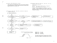
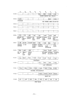
Current alarms when attempting to move each of the axis quickly are all the same (one at a time of course):
341: SERVO ALARM (X)
342: SERVO ALARM (Y)
343: SERVO ALARM (Z)
 
Last edited:
If the machine hasn't run in awhile .. Limit switches might be a little gummy .. some wd40/pb blaster on those limit switches
 
yeah, nothing changed with the switches. Do you know which DGN #### indicates the limit switches are being seen as on by the NC? I can check to see if the system sees the limit switches shorted or not.

We're short on some documentation here. I have pdf copies of the Operation and Maintenance books from Yaskawa but they are missing a lot of info
Let me see what I've got in my documentation ...
 
Of note - the machine worked, servos and all, before the battery was pulled so I am 99% sure that the servopack is not faulty, and also that the servo CPU is not faulty either... though anything can happen with these machines.

Checked that parameters are as follows:
6074 16
6075 16
6076 16
6077 0 --->we do not have 4th axis
These parameters are the same as what were downloaded from the machine when we got it, they are also the same values that are on the printout from the machine integrator (printout was included in the control cabinet)

I will check the DGN values for those stops and go from here. Thank you!!
 
Fuses good, cables good, everything moves and does what it's supposed to do unless we do anything rapid, or try to zero return etc... Every axis can move, just reaaaaaly slow otherwise it trips an alarm :/

We managed to get a copy of the parameters, we input manually to the control, onto a PC from the machine. I compared the original downloaded parameters with the values currently on the machine and I found 7 values that are different than what the original parameters were so we're going to change them this morning. They all correspond to X, Y, and Z axes.

One parameter stands out though, parameter 7002.
Original value in the machine: N7002 X- 127
Current value in the machine: N7002 X 127
There is no way I can figure out to get that value to display a negative.

Might you have any insight as to what this 7002 parameter is by chance? Is it important enough for us to care at this time?

The only thing that I can find in the Maintenance Manual is that #7000 thru #7095 are "Setting by byte by sequencer" and I have no idea what that means.

It also seems that we need to troublehsoot CP07 serial port line drivers some more because the machine is not able to receive data over RS232. We can send data from the NC to a PC but not the other way around.

Thank you for your help and recommendations!


Also I hope its ok that I'm documenting this journey, on this forum thread, in the hopes that others might find insight if they run into issues similar to this one.
 
Parameter 7002 is "check of the keep memory writing completion during ATC cycle" 1:check 0: not check
not sure why your setting was -127.
Unless its different for the mx3 .. which it probably isnt.
Either way it shouldnt be your problem right now.
Check your messages Ive got something that will help


Back
Top