What's new
What's new

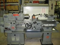
Pratt & Whitney 12 x 30 Model C - Removing apron front

I've posted here a couple times but not often. But I've gained a lot of information by being a lurker through the years and thought that I perhaps had a chance to give some information back this time.

About two years ago I restored a Pratt & Whitney 12C. It was completely disassembled, repaired and scraped. I also had custom needle bearings made for the apron which is a story in itself.

But to your question of how to put the apron front back on, you begin by mounting it and getting it into position. But before you do this get about a 3 foot piece of .035 mig wire (it is strong and slippery) and a short piece of wooden dowel rod. Make several wraps of the wire around the rod and secure it. Feed the other end of the wire through the safety interlock. Then bring the wire back to the dowel rod and make a couple wraps. You should now have a handle with a loop going through the safety interlock.

As you pull the handle with the cover lined up push evenly with maybe a light tap. It should slide into place. Then cut the wire and pull it out.

Since you have it this far, there are several areas that you should take a look at. This lathe has a very extensive oiling system in the saddle. As johnoder has said, it is unwise to assume that the oiling system is functioning as Pratt & Whitney intended. I have found in many of these old lathes that they only really wear where the oiling systems fail.

One other thing I did learn is that the clutches in the apron must be disassembled in place. There is quite a bit more to this process. Do you need more information?
 
Thanks so much. An inccredibly simple way to spring the interlock.
I agree about the oil pump. Almost all of my lines were plugged with a fine gummy sludge. Took it all apart and cleaned.
I used drill blanks for my worm needles. Tedious task to size to length.
 
Tailstock 4,
Am I correct in assuming that the worm goes back in after the feed clutch assemblies are installed?
My parts manual shows the worm assembling from the left on the 12 inch lathe. My 16 assembles from the right as the manual notes.
 
Yes, it assembles from the left, but as follows.

The reassembly of the apron can begin with the longitudinal feed clutch which can be bench assembled. Next you assemble the needle bearings on both ends of the worm gear holding the bearings in place with small rubber bands. Then as you insert the worm gear past the longitudinal clutch (which is already assembled and installed), clip off the rubber bands as the bearings begin to enter the castings.

The only part of this assembly that seemed to have any wear on mine was the needle bearings themselves. Someone had attempted to repair the oil pump and got as far as pulling the worm to the left. At some point I figure they lost 4 to 6 bearings on each end and reassembled it that way which worked but caused a clicking. This may have turned out to be a good thing as it caused the machine to be relegated to a back room so I was told. I found a company in Long Beach that was able to grind new ones in a small batch. This isn’t the last place you’ll find these bearings in this machine.

The cross-feed clutch must be assembled in the apron.

The oiling system on the saddle can be accessed by the four allen plugs on the front. Inside of these are some long oil volume rods of different lengths and sizes. Behind them are the meter valves which are screwed in. There is also a set of oil rods and galleries that can only be accessed by drilling and tapping the soft plugs at each extreme end of the saddle in the front. Drill and tap and then you can grab them with vice grips and a slide pull. As you pull all this apart, lay it all out on a table and record positions and meter valve sizes.

I don’t know if you went this far (or want to go this far) but it is the only way to ensure that it is all open.

By the way, where did you find your machine?
 
I was able to get good flow through the apron lube channels by using penetrating fluid and forced air. My lube system worked before disassemble. I cleaned out the pump and lines as a precaution.
The needle bearings are the same diameter as 3/32 drill blanks. I remember our buddy John tipped me that idea.
Took lots of patience.
I found my Model C in Fort Bragg California.
Had seen use but never abused. No rub marks on the compound or dents under the chuck area.
No missing or broken/ welded handles.
I even have the original manuals that came with it.
 
tailstock4,
I have been trying to remove the clutches on my 1957 12" C and would appreciate any info you can give. As I posted in an earlier rely, when I tried to drive out the cross feed clutch shaft the front half of the clutch pushed forward. It seems to be hung up but the worm gear is not binding on the worm. Questions -
1. Can I keep driving the cross feed shaft out the front to disassemble?
2. Is the worm assembly removed through the headstock side? Seems the only option. I'm guessing the large bushings on either end containing the needle bearings and associated ball bearings and retainer rings all slide out through the left side hole.
3. Do I disassemble the clutches before removing the worm?
Any help greatly appreciated. Also Thanks for the apron front reassembly steps. I was picturing P&W using some specialized unavailable tool.
 
tailstock4,
Had an ah-ha moment. Didn't see the tapered pin in the front of the clutch shafts. It was covered with grease and dirt. Once I drove that out I could disassemble the cross feed clutch and remove the shaft from the apron. Currently having a problem removing the longitudinal tapered pin but I'll deal with that. Looks like I've answered my own questions. I'm sure I'll have others as I progress.
 
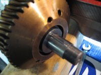
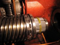
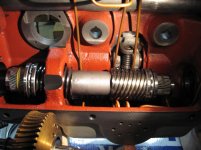
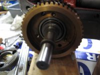
I'm at the reassembly point in my reconditioning of the apron of my P&W 12" C and need help getting the cross slide clutch worm gear installed and mating with the worm. I can see how the longitudinal clutch assembly can be bench assembled and as the worm is slide to the right it can be inserted when the middle low part of the worm is opposite the longitudinal clutch worm gear it's rotated into the worm. My problem comes down to the cross feed worm gear. As near as I can figure, the worm gear must be on the shaft with the woodruff key installed as shown in the attached picture before inserting it into the hole in the apron. I can't see any way to have the gear loose on the shaft, with the worm installed, then insert the gear shaft through the gear into it's hole and install the key. I can't move the worm to the right to its bearing but not into it so that it is angled down allowing the worm gear and shaft space to be inserted over the worm and into its hole. I also can't roll the worm gear onto the worm as I slide the worm into its right side bearing because the ball bearing assembly on the right end of the worm prevents this. See attachment. A previous post mentioned the cross feed clutch must be installed after the worm in fully inserted. I think I've disassembled it as far as I need to because the remaining bearing inside the gear again must be installed from the back, no way once the gear is in place. I hope I've explained my problem clearly enough. Any help from those that have been through this will be greatly appreciated.

One other question. I cleaned all the oil tubing and the manifold. I can operate the pump and get plenty of oil to the top of the apron but nothing so far to the two lines which supply oil to the large gears. They have very small "metering" plugs in the line where they exit the manifold. Are these metering plugs with the 4 very small holes designed to limit the oil through these 2 lines and will function better when reassemble and operated as designed?

IMG_0963.jpgIMG_0964.jpgIMG_0965.jpgIMG_0967.jpg
 
greenmtfan,

You are on the right track as far as the cross feed clutch assembly goes. It’s a little hard to remember the detail steps I used two years ago but this is how I remember it. The clutch shaft mounts in the back of the apron first. On the left side of the apron there is a bushing that holds the needle bearings. Seems like you can leave this bushing off but the thrust bearings and their races can be on. Have the needle bearings on with rubber bands securing them on both ends. This should give you some maneuvering room as you simultaneously install the worm and its bearings. It all goes together simultaneously while you are manipulating the worm and brass worm gear. You will need to have someone else cut the rubber band as it goes in on the right side. Then you can reassemble the left side bushing. The clutch has to be completely disassembled before you begin.

As to the other part of your question, on the top of the apron, I think there are two discharge holes. These should have little flat rubber gaskets in the recesses of these holes on top of the apron. You can temporarily block these off with a piece of rubber and something like a parallel that is clamped to the some of the threaded holes on top of the apron to make a temporary seal over those holes. Then you can actuate the pump and the oil should flow through the apron.

This brings up another issue. There are quite a few metering values of various sizes in the saddle. These can’t really be cleaned or blown out. They just need to be replaced because once it is back together oil needs to be restricted in the right amount in the right places for it all to work correctly.

While you have this apart, is your feather key in the worm in good shape? This would be the time to replace it. I decided to put in a new feather key. I used a jig design provided in one of johnodor’s postings and modified it to fit the Pratt & Whitney. It worked well.

I have pictures of the rebuild. If that might be helpful, maybe I can figure out how to post them.
 
Tailstock4,

Thanks for the reply. Every little bit helps and I was finally able to reassemble the cross feed worm gear to the worm, and reassemble the other components of the apron. I sure learned a lot reconditioning this part. I checked the feather key in the worm and it looked good. Time will tell. I also appreciated your before and after pics. Great job. I know what you went through. I was surprised, your choice in colors looks identical to mine. Thanks again for your help. I know I'll have many more questions before it's over.
 
Hopefully this is the last question I'll have pertaining to the apron.

When disassembling, there was what appeared to be a thin layer of sealer from the bottom up about 3". I assume this was to prevent the oil in the sump from leaking out. When you reassembled, did you reapply any gasket material or is the metal to metal surface accurate enough to prevent the oil leakage. Thanks for the help.
 
I would use a small film of Permatex at least like you say maybe a third of the way up.
I have been following this thread closely and now I am in the process of putting my apron back together.
Apparently the 16 inch Model C is a lot different regarding the worm/worm gear assembly. The worm is removed from the tailstock end. Also I removed my feed clutch and gear units assembled.
 
I installed the worm and apron gears in my 16 inch yesterday. Installed worm from the right or tailstock side in fargo enough so that the relief for the center of the worm was beneath the location of the cross feed worm gear. The worm in that position allows the gear and fully assembled clutch unit to be installed.
After that the worm and gear can be engaged by moving the worm to the left as the gear turns to complete the worm assembly into the pressed bushing on the headstock side.
The comes the longitudinal feed gear. With the clutch unit fully assembled use a soft hammer and tap the shaft on the end with the Woodruff key through and out of the gear. Now you have the gear. Keep track of the beveled thrust washer on the back side of the gear. It needs to line up with it's Keyway to the shaft when you instal it. I pasted mine to the inside of the apron lining it up carefully with sticky grease.
Now set the worm gear on the worm, line up to the bore in the apron behind the gear and install the shaft.
Done.
Next I installed the apron pinion for the rack from behind the apron into the corresponding gear that meshes to the gear on the longitudinal clutch.

That's it for the 16 inch version.
 
Okay. Apron back together.
I used the MIG wire trick previously posted in this Thread. My wire was .025 and plenty strong enough. I looped around the interlock shaft one time, to keep it in place, just beyond the collar that compresses the spring.

It took at least a half a dozen tries that failed for whatever reason. I had the half nuts disengaged to open the detent on the half nut interlock collar and of course the longitudinal and cross feed clutches were in the disengaged position.
Eventually I pulled the wire at just the right time as a successful smack with a deadblow hammer set everything home. I still can't say what is the Pratt and Whitney method, but I succeeded.
Then I held my breath the wire wouldn't break as I pulled it out. Being one turn around the interlock shaft way inside the apron was concerning from the beginning. With considerable force it finally slipped out. If ever again, I would recommend grease around the shaft where the wire was wrapped to help it slip.

To check that everything ended up in the right place I installed the Longitudinal clutch handle first and checked. It worked. Then came the cross feed clutch handle. What a bear! The pressure to depress the clutch mechanism enough to line up the pin through the handle was about equal to the struggle of assembling the cover.

Sorry for the long story, but my hands are SORE!
 
I just removed the QC gear box on mine this past week. Found one of the 7 3/4" socket head cap screw bolts holding it on was sheared off at the threads. Also discovered both fingers that operate the oil pump were cracked off so I'll be fabricating a new oil pump actuator. Can't wait to start assembling the parts I've spent the last 7 months cleaning and painting. The headstock, bed and legs are next but I am going to leave them assembled, just clean and paint. Thank you for describing your assembly of the apron front. Hope mine goes as smooth.
 
One real struggle was installing my cross feed clutch engagement handle while inserting the eccentric screw through from the right.
It finally went in but required a lot of spring pressure to depress the clutch mechanism enough to line up the pin.
I recall when removing that handle that it was under considerable load.
The longitudinal handle was way easier.
 
The Pratt and Whitney Method

I was going to start a new thread, but decided it would be best to keep this information in one place for future searches. I'm finally going back together with my PW Model C, 14x54 that rolled off the assembly line in around June of 1941; serial number 656. I was intrigued when Conant wrote "I still can't say what is the Pratt and Whitney method.", so I spent some time imagining if I was working at Pratt and assembling these machines, what was the method?

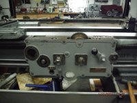
The trick/method is to pre-assemble the interlock into the cover before hand. Then, slide the saddle off to one side so you have access to the top of the apron. It's only 8 screws and since you're lifting one side of the saddle it's not too bad to pick up and slide it over. Then using some all thread to act as guides, you can slide the assembly on and reach down thru the top with a long slender screwdriver and push the interlock over to slide over the longitudinal feed collar ramp. This was so easy I was sure it is the PW method.

Dscf8140.jpg
DSCF8139.jpg
DSCF8136.jpg
DSCF8142.jpg
DSCF8143.jpg

I used a sealant called "Hondabond" on the lower quarter of the cover to address oil leaks. I've had good luck with it working on motorcycles with metal on metal sealing surfaces and it has worked well on machine tools also.

I hope this helps anyone working on these old machines.

Mark


Back
Top