What's new
What's new

Resurrection of a lobotomised Maho 600T

The new servos I got with the machine are:

X+Z (Maho): Leadshine ELM1000FM80H-SS, 3.18Nm @ 3000 rpm
Y (Maho): Leadshine ELM2000EM130F-H, 7.7Nm @ 2500 rpm

I got a (German) manual with the machine. The below pages are from that one. In the first you can see the "nominal" torque of the original motors, the transmission (gear) ratio and in the second one the adjustment instructions for the slip clutch.
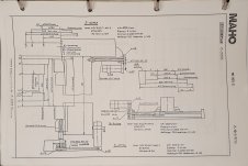
20230312_211151.jpg20230312_211258.jpg
So at least on paper, the torque of the new servos are on par with the original ones. Base on the original servo motor data sheet, I had a feeling that the original servos would have had more peak/dynamic torque. But based on the Y-axis (Maho) slip clutch setting, maybe not, . In fact, the Y-axis (Maho) transmission ratio is 1:3.27, so the 8 Nm "nominal" torque on the drawing would translate to 26 Nm, which would just barely cause the clutch to slip.

There are two things I don't like with the new servos. The rotational inertia is quite low for the X+Z (Maho) axes, which could lead to stability issues, and the drives for the same only accept step + dir inputs. The Y axis (Maho) drive accepts analog +-10V, which is what I would prefer. I have ordered a Mesa 7i95T card which uses step + dir, so that is what I will use. There is a risk that LinuxCNC would start trying to correct for a slightly incorrect position before the drive has even "commanded" the servo to move there. But others have apparently got it to work. I guess the closed control loop in LinuxCNC just needs to be slow enough that the servo/drive loop is faster.
 
Would expect this to be assembled dry. It only moves when there is a crash. Oil or grease will squeeze out over time changing the set breakaway.
Might consider dry graphite spray on the friction surfaces which will remain constant and potentially prevent corrosion on the friction faces.
Cheers Ross
 
Yes, I would also be inclined to think it should be assembled dry. What I did not write was that when I disassembled it, there were a significant amount of oil on all the surfaces. I believe this was because of the disintegrated ball screw seals. I fear that if I had assembled it dry, oil might again get there from the ball nut, which would tend to lower the breakaway torque. I did renew the seals, but the inner lips of the seals are running on a bushing, and between this bushing and the ball screw shaft, there is no seal. So oil might get past even with good seals.

I don't want the table to come crashing down because of the friction clutch slipping. This is in my opinion a bigger concern than crashing the machine by direct operator (=me) mistake. Now, most likely the friction clutch would start slipping noticeably before suddenly "dropping" the table. Still, if I crash the machine I have myself to blame, and have to accept that. If the table suddenly drops to the base and destroys something, there is not much I can do about that. Except make sure that the clutch tends to tighten over time rather than the reverse :)
 
It was interesting watching RotarySMP's video. I've done similar retrofits in the past and I could see for this specific machine the value in going the route that he did, especially since this machine doesn't even have a toolchanger, much like retofitting a CNC grinder. What is really nice about Mahos and Deckel Mahos, as well as early DMG machines is the external E-Stop chain. That is significant safety that you don't even have to think about that is retained without having to recreate it via logic in the control itself. If you hit the E-stop button, the machine will stop no matter how messed up the control install may have been. Most controls aren't like this so this alone is one of the reasons why a Maho is a great candidate for retrofitting, from an electrical standpoint. Mechanicals and glass scales obviously set it several leagues beyond any of the cheaper stuff out there, I personally cannot imagine why anyone would start with a hobby machine but then again my MC800H weighs 40,000lb so obviously size and weight matter more to some than others.

Now, if you have a VME based control, something 532 or early Millplus, I strongly advise against a retrofit and reach out to a few of us here on PM and we might be able to help you repair what you have, even the 432 CNC5000 controls may be worth repairing. The VME controls have amazing capabilities with some pretty great trajectory planning that allows the machine to maintain cutting accuracy even if the G-code is calling for motion that will cause unwanted servo acceleration and deceleration. Try this with an older control, like Fanuc and you will hear the mechanical's taking a beating during an elaborate feedmilling operation or other high speed milling op, I wonder how well RotarySMP's retrofit handles this. There are somewhat more industrial PLC controls that are available too that might be worth considering that could make the machine more valuable if it were to be sold one day. I picked up a Siemens 802C control for low cost that is setup for driving analog amplifiers and still is an industrial control, when I have people looking at machines a DIY retrofit control can really kill the deal, after all, what has been done and who can support it? When we do these projects it's easy to think we'll keep the machine forever but this is a "hobby" that can turn serious pretty quick and next thing you know this machine is out and more and more bigger and better machines take it's place... and start making you money in the process.

Best of luck with your project!

Nerv
 
Just a note on "table crashing down":
as I have worked on the servo of my FP4AT some, trying to figure out issues, I had the servo out several times.
I found that the "Z" (Deckel Z is table up/down) with servo removed will slowly run downwards by itself, but not accelerate.
Looking at it, it looks like a slow downfeed of constant speed. It does not accelerate. If it would, that could be bad.
In this state it can also be pumped up with a jack, which can be useful.
So my point being that both brake and clutch have to hold very little to just hold the Z in position.
Its not like there is a huge force constantly stressing things.
A clutch gummed up with old oil will be almost unreleasable, so any torque value will be pointless.
 
While there is really not much left of the original E-stop chain, I do plan to recreate a similar one. The only thing I'm not sure of at the moment is if I want to remove the power to the servos directly, or with a small delay. With the delay, they might brake for a bit (the documentation is not 100% clear) instead of free coasting. It appears that the Maho was short-circuiting the servo armatures in an E-stop situation. But I don't think the servo drives would like me if I did that here. I might do some tests later on to see if the delay is worth it.

Regarding the control system, I will stick with LinuxCNC. Like you Nerv say, there may be better ones out there, especially if taking the resale value into account. I have also heard about the Siemens ones being fairly affordable. However, I'm not much concerned about resale value in this case, even if it would go out as scrap one day. I also have some experience with LinuxCNC from a couple of other machines. And if I later want to add capability like a 4:th axis, rigid tapping, I know that LinuxCNC can handle "at no cost". LinuxCNC has the G64 Path Blending G-code, which may be similar to what you spoke about in the VME controls.

I may have to revisit the Y-axis (Maho) slip clutch at some point. If the table indeed falls down at more or less constant speed, maybe my fear of the clutch slipping is unwarranted. I might have to do some tests on this as well when I get the machine back together and the servos/brake powered.
 
Don’t think any delay in shutting off the servo’s is something you would want.
Need motion and power off immediately.
As to freewheeling on the vertical slide , think the rate of movement has much to do with the state of repair of the elevating screw. ( ball screw).
Will add that on my daily driver FP4NC I had a weak brake within the “Z” servo such that the vertical slide would creep down when power was off.
Movement would continue till the screw bottomed out( could damage the ball nut)
Was bad enough that it prevented use is the control graphics. When selected turning the graphics on the servos are turned off. When this happened the vertical drop would trigger an “E” stop
(Detected slide movement with no movement command)
With power off only way to stop the slide from dropping was to pull out the hand wheel. (mechanical handwheel friction device was enough additional friction to hold the slide)

Finally cured the problem by replacing the servo(e-bay) with one that had a good brake.
Cheers Ross
 
Delaying powering off the servos can lead to a shorter braking distance. But that requires that the servos support it, handle it fast enough, and handles it safely. It's difficult to be confident about at least the last part with the Leadshine ELP drives I have. So yeah, maybe it's best to just cut power immediately.

On my MH600T, I believe there is a mechanical stopper for the vertical slide that takes the load prior to the ball nut clashing with something. Anyway, I need to investigate this a bit more once I have the saddle and table back on.
 
I have been travelling over two months since the last post, so progress have been slow. In any case, I started cleaning the parts and put the saddle back on the machine.

The parts are cleaning up nicely. I used Mirka Mirlon product with (I guess) a grit equivalent of 1000 paper, and only light pressure on the sliding surfaces. It didn't take much work at all to get the brownish/red color off the surfaces. But there was quite a lot of crud in the oil bores and channels, so I'm happy I decided to go for this cleaning.
20230619_164414.jpg20230620_161525.jpg

On the vertical slideways you can see the difference before (left side) and after this light "polishing" (right side).
20230620_150938.jpg

I put the saddle back on the machine. There some small galling on one of the sliding surfaces. It's not bad, and I don't plan to do much about it. But I might order some of the precision ground flat stones to go over and make sure nothing is sticking up too much.
20230620_193508.jpg20230620_193523.jpg
 
After some more travelling, I am now back home and on vacation. So hopefully there will be some more progress.

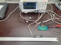
I mentioned in passing that I will make my own "EXE" converters or interpolators for the Heidenhain linear scales. Last week I soldered the components to the board and tested it out with the vertical scale. The smaller IC to the left on the board is the iC Haus iC-NV sin/cos interpolator and the one to the right is a MC3487 differential line driver. The latter one can be left out to use single ended signals. The output terminals on the right can be replaced with an ethernet jack, and that is what I intend to use in the end. Pretty much everything is configurable with either component values or solder jumpers.
20230719_091055.jpg

In the below photos is the measurement setup for the test. The yellow channel on the oscilloscope is the direct input from the Heidenhain scale and the blue channel is the output from the iC-NV chip.
20230719_090811.jpg20230719_090844.jpg
The yellow signal would be a sine wave if the linear scale head was moved at a constant speed, but for the test I just pushed it by hand. In any case, one period (should) correspond to 20 µm of travel. And during this period, five output pulses/periods are generated. Only one of the sin/cos channels is shown on the oscilloscope, and when the other one is also used, a total of 10 output pulses is generated for every input period. This gives a total of 20 edges to detect, and thus a resolution of 1 µm.

I plan to make the design freely available. But I think I may do a revision of the board first. It appears I forgot to put the component values and some explanations on the silk layer, and I would like to add those. And maybe I will also add a small inductor to the power input, to help with the crowbar circuit (which blows the fuse in case a too high voltage is applied). And I may try to add a ethernet jack possibility for the linear scale side as well. But it may not be so easy to make it fit, as I want to stay with the current 50x100 mm board size.
 
Hey there Finngineering,

thanks for the documentation, following this thread with interest.

A, slightly off topic, question if I may: I have, yet, to understand the 'interpolation' that HH describes in the 'interpolation and digitizing electronics' datasheet. Could you please explain where the term 'interpolation' fits when we're talking about converting an analog waveform to a digital pulse series? (your term 'converter' is not by accident I am sure)
(is it that they are talking about interpolation in time of the digital pulse series to elongate them for when the scale is moving slower than maximum allowed motion rate? In your nice scope capture we can see that, for the slower of movements, the corresponding pulses are longer. Is this the 'interpolation'?)

Thanks in advance.

BR,
Thanos
 
If you want the one sentence explanation, it's in the last paragraph of the post... I start by explaining how the linear scale works as a build up for the explanation of the interpolation. I'll leave out the index/reference mark, because it is not important for this discussion. I will also simplify the output of the scale to be +- 1V instead of the 11 µA (peak to peak) that the LS 403 actually outputs.

At every position of the scale, the read head outputs two separate voltages. For the first of those voltages, you could think of it as a sine wave "drawn" on the side of the linear scale and repeating every 20 µm (for LS 403). The read head outputs the (first/sine) voltage according to the position along this sine wave it's currently at. The second or cosine output works exactly the same way, but as this is cosine, the wave "drawn" is offset by 90° from the sine wave. In other words, it's offset by 1/4:th of a complete cycle, or in this case 5 µm. Below is a representation of this for one cycle, equivalent to a travel distance of 20 µm. But this repeats over the length of the linear scale. You can see that the waveforms line up if you would stack several of the graphs side by side.
Interpolation.png

So the base "cycle" of the LS 403 scales is 20 µm. But from the above graphs, it's possible to determine the position to a higher degree of accuracy than 20 µm. This is what the interpolation does. As an example, let's say the first/sine output from the scale is +0.5 V. We thus already know that we are either at phase 30° (1.7 µm) or phase 150° (8.3 µm). When we take the second/cosine output into account, we can determine which of the two possible positions is correct. So if the second/cosine output is around +0.87 V, we know we are at the 1.7 µm position, and if it's around -0.87 V, we know we are at the 8.3 µm position. For any output voltages, the exact position along the graphs above can in theory be determined. Note also that for a specific first/sine output voltage, there are only certain second/cosine output voltages "allowed". So you cannot make up two voltages freely and try to find the position based on those.

Now that we know a more accurate position, this can be delivered to the control system in a number of ways. For instance, we might imagine an "A" digital output that is starting high at a position of 0 µm, changes to low at 2 µm, back to high at 4 µm and so on for every 2 µm. Likewise, we could have a "B" digital output that change to high at a position of 1 µm, back to low at 3 µm, high again at 5 µm and so on. This is pretty much what Heidenhain would call an EXE converter with 5 fold interpolation.

TLDR: The interpolation is a way to determine a more accurate position than what the base "cycle" of the linear scale gives. I guess exactly how this is done is implementation dependent (meaning there is some freedom to chose exactly how this is done).
 
Hi there, thanks for the elaboration.

I am surprized that they used a strict technical term like 'interpolation' so loosely under Dr J's supervision. The fact is that, of course, 'interpolating' an analog waveform makes no sense, interpolation has meaning only on a discrete set of samples (actually, interpolation is mostly used as one way to kind of 'retrieve' the shape of the initial analog waveform when only discrete samples are available, after sampling that is). What they are doing in order to get a better granularity is just sampling more 'often' spatially compared to the sin/cos period.

Given that, trying to dig into their minds, I think that this could have been a historical thing. Possibly, first displays only understood full periods of the sin/cos and later on they managed to get samples in between and they considered 'interpolation' a better word than 'oversampling w.r.t. the grating' or something like this for describing the improvement.

I'll stick to the term 'converter', 'digitizer' and so on :)

Cheers,
Thanos
 
The seals were completely shot and the bearings certainly had their fair share of crud on them. I cleaned the parts and put new seals (normal lip seals), repacked the bearings with grease and put everything back together.
Surprised that you didn't buy new bearings. Good quality ones cost very little, hardly worth the effort of putting back something that might be damaged.

The scraping/flaking/half-mooning on the ways looks fantastic, as long as the spindle bearings are good you'e got a great machine there.

I'm curious, where are you located?
 
The term interpolation is maybe not all that clear or even correct. But it does hint at the function it performs. I also thought about this before putting that term on the board, but did not come up with anything better.

Regarding the bearings, you are probably right ballen that it would have been worth replacing them. And maybe I still will, now that you point it out. I'll give it some thought. In any case, the original bearings had no chips or such in them. And they did feel good both before I cleaned them and after. But given that there was some slight pitting corrosion on the faces, there could of course be something in the races as well.

I'm located in Finland.
 
Regarding the bearings, you are probably right ballen that it would have been worth replacing them. And maybe I still will, now that you point it out. I'll give it some thought. In any case, the original bearings had no chips or such in them. And they did feel good both before I cleaned them and after. But given that there was some slight pitting corrosion on the faces, there could of course be something in the races as well.
Modern FEM, CAD and CNC methods have had a big impact on standard bearings. The ones being produced by the bearing companies like SKF and NSK have got better materials, better seal designs, and significantly higher precision than 50 years ago. Many of todays standard bearings are as precise as the precision bearings of those days. And in standard sizes they typically cost 5-15 USD or Euro. So IMO it is not worth spending the time to clean and inspect a 50-year-old standard bearing. If I have them out or accessible I just replace them.

Of course it's a an entirely different story for spindle bearings.
I'm located in Finland.
Welcome to NATO... though I'm sorry that it had to come to that.

Cheers,
Bruce
 
One reason I opted to reuse the old angular contact bearings was that I was not sure of the exact type of bearing to use. I recall from the past that at least SKF have different variants of the angular contact bearings (I'm most familiar with SKF). It's clear to me that the bearings should be universally matched. What is less clear is the contact angle, and what grade of preload/clearance to use:
skf_angular_contact_bearings.png
https://www.skf.com/group/products/...ular-contact-ball-bearings/designation-system

I would assume some amount of preload is what I want. By looking at more accurate data/tables, I could likely figure out exactly what I want. And then I need to find somewhere to buy those bearings. At the time and with the old bearings feeling good, it didn't seem worth the effort (and risk of a mistake and putting in the wrong type of bearings). But now that you point it out, I'm not so sure anymore. To change those bearings later most likely requires a similar state of disassembly to what I have now.

Thank you for the NATO welcome. Not that I have ever really worried. But with the current state of affairs, I think it was the right time to join.
 
There are people here (Ross, others) who know a lot more about bearings that I do. So I suggest you post a list of the bearing numbers/types and a few words about their function. You should get some sound advice.
 
Time for an update again.

I haven't quite made up my mind about the Y-axis ball screw bearings yet, but I think I will leave it as it is. The Maho spare part number is 27.069340 with description "L20 DF 030 T manufacturer-name-which-PM-doesn't-like". In this catalogue:
Bearing catalogue
I found a bearing with correct dimensions (as I recall), with manufacturer number 7602030TVP. At least some similarity with the Maho spare part description. Based on a quick google search, they appear to be a bit pricy at over 150€ per bearing. For the time being, and while it's still possible that something comes up that will make the whole machine worth its weight in scrap prices, I prefer to not spend more money than I need.

The last two weeks or so I have been working quite much on the Maho. But mainly on the electrical side. I have made a new circuit diagram (not 100% finished yet) and working quite much on the layout to get everything to fit on one back plate inside the cabinet (except the spindle VFD, which will have to be external). Below is how the layout looks now, and I'm sufficiently happy with that. The latest draft circuit diagram is attached to this post as well.
20230824_164914.jpg

I started cleaning up the X-axis slide as well, and the slide part appears to be in good condition.
20230818_195915.jpg
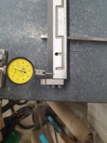
On the "clamping bar", I thought I could see a bit of scratches, potential wear. Just for kicks, I tried measuring it, but I don't get fully consistent results. If somebody has a good suggestion for an indicator stand (which I can buy in Europe), I wouldn't mind that at all. This stand is a bit clumsy and rough.
20230824_200511.jpg

The gib clearly has a bit of wear towards the ends.
20230824_203027.jpg
Again, I was interested to know approximately how much. First I tried to stand it up on parallels and measure (underneath) to see how much it bulges in the middle. It turned out there is a slight bow to the gib, so it can't be measured like this. Flipping it over and cancelling out the bow is in theory possible, but the scraping marks makes it difficult to get enough consistency in the readings. But based on the (presumably) unworn stripes at the edge, I would say the most worn part is approximately 0.01 mm low.
20230824_202916.jpg20230824_202933.jpg

Next on the agenda is to start wiring the panel and also put the X-axis slide back on the machine. Then I should be able to start moving the X-axis under power, and at least get a feeling for how well the servos will work.
 

Attachments

  • maho_mh600t_cnc_draft-2023-08-24.pdf
    228.8 KB · Views: 4
Think it’s usual practice to straighten gibs before attempting any work or evaluation.
As to indicating on a scraped surface I use a gauge block between the scraped surface and the indicator finger.
Normal wear usually happens at the ends of the slide or gib.
That is why when reconditioning a slide or gib it’s usual to relieve the center by several scraping cycles.
This will extend the useful service time of the slide.
Cheers Ross


Back
Top