Antoine21130
Aluminum
- Joined
- Oct 19, 2023
Hello everyone,
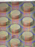
Have a issue on my Matsuura MC-660-VG (Yasnac j300) when machining 3mm rounds on aluminium using 3mm carbide end mill. My tolerance is set to 0.01 in fusion 360 and everything in the simulation looks great. When machining, the rounds have some visible segments and some of them extend more than the round I need to do (you can see the extension on the round at top left corner of the picture below).
Machining at 600mm/min so I don’t think speed is an issue.
Also have a weird behavior on the chamfering that I don’t have in simulations either.
Thanks in advance !