What's new
What's new

Took on a repair job for a broken bicycle bottom bracket (ww2 Swiss army bike)

Bore hole in each piece for a steel locating pin like what was stated before.
Now a professional welding place could mount that to a rotating fixture and make a perfect set of beads. They might even recess the fractured line to get deeper
weld penetration. Then maybe grind it or leave it as is.

My BMW motorcycle had a worn a gear at the rear wheel where the drive shaft connects. The gear section was cut of and a new gear welded on as described above.

Silver solder is the way to go here. This part is probably hard enough that a file won't mark it.

The spline coupling for the wheel on those bikes is a known bug. I've always thought I would try to wire EDM a new spline and silver solder that to the ring gear in the
bevel drive. I *think* you can buy the new female wheel spline couplings.

The /2s only have one kind of wheel, the front wheel has the spline on it too. That way the sidecar rigs only have to carry one spare wheel. Fits front, or back!
 
Silver solder is the way to go here. This part is probably hard enough that a file won't mark it.

Given that typical tempering temperatures for non-hot-working steels are in the range of 400 to 600 degrees and hard silver solder (55%) requires a soldering temperature a little above 1000 degrees F, how can one maintain proper hardness while silver soldering it? As an example,O1 typically fully anneals in the region of 1170 degrees F.

Denis

Welding something that might be high carbon steel is a riskier proposition. Good chance you could wind up
with a brittle part.
 
Welding something that might be high carbon steel is a riskier proposition. Good chance you could wind up
with a brittle part.

I am not suggesting welding either, though using a proper filler and proper heat treating could have a decent chance at making a durable repair. But silver soldering is a total non-starter due to softening of the spindle not to mention the soldered joint being intrinsically weaker than virgin tool steel correctly hardened and tempered.

He needs to fabricate a new spindle as I suggested above or purchase a new or good used commercially fabricated part. Any other method of patching together the pieces just is not as strong as a properly heat treated part made from scratch.

Denis
 
Not visually correct, but since that is a cottered Thompson BB you may be able to buy a drop in:
Sunrace Cottered Thompson Press-Fit Bottom Bracket | Axle Length 136mm

I suspect this is a perfectly manufacturable part (although not sure who I would contact for the fixed side bearing race grind), but another option would be to repair this one in a cosmetic only manner, then fab a cartridge bearing replacement spindle and cups. Harder would be making the outside look like it still had an adjustable cone in it, and of course it would no longer be period correct.
 
Concur that a repair is unlikely to work.

That part is really pretty heavily stressed. I have a Lambert, which originally had a square socket in the crank, fitting a square end on the bottom bracket shaft. I remember shearing that square shaft end right off, and that was back when I did not weigh nearly what I do now. Sheared from plain pedaling force (torque).

Lambert warrantied the shafts and replaced them with the traditional taper design.

I strongly question the idea of any repair holding, short of a good weld, and that opens up enough other issues that it appears to be easier to remake the part and make sure to avoid stress risers.
 
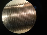
As is the norm around here, I’m overwhelmed by the outpouring of help and insight! Thank you. I thoroughly enjoy reading the input and I learn from each. None but an old (still in the box ) Starrett thread pitch guage kit had a 24 pitch gauge which lined up well. I don’t have an optical comparator, nor a bunch of skill. I looked under my microscope and saw that the 24 pitch lined up will but the root and the crest of the thread have some radius. Going by the Gauge, I think it is a standard 60 degree thread form.

I suggested the customer buy the original part from the Swiss site posted above as it was the exact looking spindle at 131 mm long and with 17mm 24tpi threads, both sides used lefthand threads (I don’t understand that)

I don’t single point a lot but my 15” engine lathe is setup for metric threading. I think I have inch change gears around somewhere but I have never used them. for 50 bucks, buying an original seems sensible.

I have never single point threaded left hand threads but I assume it’s a matter of mounting the tool inverted and running the lathe spindle in reverse. I’d choose pre hard 4140 which I enjoy machining anyhow since it doesn’t deflect a lot and produces a nice finish.

I don’t look forward to changing the lathe to inch threads but making the part looks fun. The kind offer with thread cutting is very appreciate and I would ask for that help if I were to be unsuccessful. Buying a real original for 24 euros plus shipping makes machining one a little silly.

I did remove the other bearing race once making a collet to clamp the OD in my hydraulic vise. It was on tight-tight and I expected right hand threads on one end and left on the other, not the left-left this spindle has. Welding the unknown steel is risky and any inserted key will be less robust than the original no mater what. I may try that anyhow just as an intermediary fix.

Thank you again for the insights, I enjoyed each one. The depth of knowledge in this forum never ceases to to be amazing to me!
 
The bearing races have to install perfectly parallel and the spindle does get a pretty good workout with cyclic torque and bending forces. Probably not good to weld it.

If you can buy one that fits exactly that would be the best, obviously. Else, the threads with the rounded root and crest might indicate Whitworth threads, common on British bikes up through at least the 70s. If so, those are 55° thread angles.

If you do fabricate, you might want to ask on Bike Forums, on the bicycle mechanics or vintage bikes subforums. You also might want to noodle around the site Sheldon Brown-Bicycle Technical Information. The late Sheldon Brown put an enormous amount of useful information into his website. You could use it to find dimensions, hints on the thread size and spec, and other stuff.

BTW, the way that the crank arms are fastened onto this spindle is by the use of cotter pins. That is, this is called a "cottered crank" arrangement.

The ebay add below has a similar replacement, with dimensions. May be helplful.

Thompson Thun Type Bottom Bracket | eBay
 
This is a very old design. One key difference between this thread and newer designs. In modern designs the cones are machined into the axle and face outward (the bearings are outboard of the cones). The cups (one per side) screw into the bottom bracket shell. The cup on the drive side (the chain side, normally the right) screws all the way in and is torqued in place. Bearing balls and grease go into the drive side cup, and the spindle is inserted. Then a cup on the non-drive (left) side is greased and has balls stuck in place and is screwed into the bottom bracket until proper preload is attained. Then a ring locknut is used to fix the non-drive side cone.

In your friend's design metal cups are pressed into the bottom bracket, and grease is applied an bearing balls added. The the spindle with one cone is inserted. The other cone is screwed on to get preload, and a locknut is applied.

So, in modern bearings the cones on the spindle are machined in and push the bearing balls outward. The cups screw on and compress the balls inward.

In your design the cups are fixed in the frame and push the balls out. The cones on the axle are adjustable and put the balls inward.
 
I have never single point threaded left hand threads but I assume it’s a matter of mounting the tool inverted and running the lathe spindle in reverse. I’d choose pre hard 4140 which I enjoy machining anyhow since it doesn’t deflect a lot and produces a nice finish.

I don’t look forward to changing the lathe to inch threads but making the part looks fun. The kind offer with thread cutting is very appreciate and I would ask for that help if I were to be unsuccessful. Buying a real original for 24 euros plus shipping makes machining one a little silly.

BTW, that is not how you make a left hand thread. In fact, that is my preferred way to cut a right hand thread especially when cutting them to a shoulder.

My lathe has a simple selection on the gear box for left hand vs right hand threads. I guess yours does not, so you will need to engage manually a reverse tumbler arrangement which many change-gear lathes have.

Denis
 
... the threads with the rounded root and crest might indicate Whitworth threads, common on British bikes up through at least the 70s. If so, those are 55° thread angles...

Bosley, if I may quote myself from page 1 of this thread:

"British cycle threads were all 60° angle, though the root and crest radii were different from Sellers and Metric threads. They were originally called CEI threads, for Cycle Engineers' Institute. In 1950 they were rationalised and adopted as BSC, or British Standard Cycle, threads." A profile drawing is here: British Tools & Fasteners - BSC Thread Profile

If there are 55° Whitworth profile threads on a British bike, they will be part of a kludge as sometimes carried out by a teenage me when I couldn't afford BSC taps and dies...

Reading round the interweb, it appears that British cycle threads were widely used in many countries, so it is very likely that the OP's thread is indeed a British one.

George
 
The fracture is a "bending fatigue fracture," normal to the application where pedaling to go forward applies a bending load in one area and braking applies a bending load on the shaft in a different location. The torsional load is not significant.
 
To make a left-hand thread, you reverse the leadscrew, not the spindle. Turn the compound to 29.5° or whatever your preference is to the other side of 0 from what you use for right-hand threading - e.g., for right hand threading, the compound is angled like this: \ but for left-hand threading, angle the compound like this: /
 
"silver soldering is a total non-starter due to softening of the spindle not to mention the soldered joint being intrinsically weaker than virgin tool steel correctly hardened and tempered. "

1) there is no information about the state of hardening or tempering on the original part. Good chance, given that
the cones are not part of the spindle, it is not heat treated.

2) a properly designed silver solder joint (with the internal steel pin as mentioned above) will develop the full strenght
of the original part. Remember is not just some globbed on brass weld. The joint has to be correctly toleranced and
the internal pin needs to be the correct size. The strength does not come from the face joint of the original parts.
 
429400BC-8D75-40D6-A6E4-9FBA93E630B0.jpgI’m not surprised by the level of help and experience here, I am surprised by the amount of odd thread sizes. I guess I need to try to turn LH threads, never thought I’d “need” to. I suggested my buddy get his customer to buy the one from the Swiss site. If that won’t work I’ll make one from 4140 pre-hard. I may try welding this one just because. I also can’t see how it would work for long.

Thanks for the thread references, none actually line up with what I have. It’s for sure 24 tpi but if it’s 59 or 60 degree, I can’t tell. The following is a photo from my “high tech” inspection equipment (iPad photo of the eye piece). The thread is 17mm. It looks like a radius to me but the picture isn’t really showing that very clearly.


Back
Top