What's new
What's new

Monarch Series 61, Rebuilding for Improvement

There's a Monarch brochure floating around somewhere, I'll have to see if i can find a link. In it Monarch gave a claim to the depth of hardness on flame hardened beds. On the low side maybe 1/16" ?, but it memory serves i think it was closer 1/8".

I dont believe this bed was ground before. Im guessing ground zero to be in the vicinity of .020" when I'm done grinding, and still well within the harness range.

On finish: prior to begining i had long expected to have in issue where sled may hit a piece of grit, justle, whatever, and create a bump or bad spot in finish. Knock on wood, i was scared for nothing. That has not happened a single time, and i wipe and re-oil sled ways about every 3rd pass, and there is some dust in old oil when wiping. This portion is actually so good that I'm frankly shocked.

The miscues i do have are so minor i dont care, and usually wipe out in one or two passes. The miscue comes from the hoist/winch when I'm in the middle of a pass. That problem is cable as it spools into the spool on hoist. The cable tends to wind toward one end of the spool. As the winding of cable grows tall on one side of spool, every once in a while the cable will drop off the tall group of winding, to the lower end of spool. That sudden slack in cable causes a split second stop of sled progress, which leaves a minor spot where grinding wheel had a chance to dig more.

I seem to get that miscue about once every 3 to 5 passes. Wiping and lubing sled ways more reduces it. The sled rolls with little tension when new oil is put down.

If you'd like to solve that problem, re-spool with a very thin steel cable. You certainly don't need much tensile strength in this application. Alternatively you could use the winch drum with only a few wraps around and the tail of the cable loose out the other end so that it acts like a capstan for the finish passes. You'll need to maintain a light tension on the tail end of the cable.
 
Know you don't need more jobs - and if I were you - I would be focused on sticking with what's working - so feel free to take this with a grain of salt.

Suspect from the issue you described - you are using a winch without a cable tensioner.
That's the flat metal spring that presses down on the cable and helps keep it wandering back and forth no more than one wrap deep.
Your handle has both Texas and Gear Train init - so I'm probably singing to the preacher on this one.
Here comes my song...

When pulling something without the spring tensioner - the cable has a tendency to grow on one side - before sorta popping off the built up area.
Worse - and this is why I'm taking a moment to type - every once in a while - at the critical moment - the damn thing will go full awol, jumping off the spool and tangling itself in a reliably horrible manner between spool and winch framing.

All this to say - seems like you got it going on right now - have adjusted your method to account for the imperfections - and are almost home. Just something to keep an eye out for if you are getting build up on one side. Everyone rooting for a great outcome here.
 
If you'd like to solve that problem, re-spool with a very thin steel cable.
This is tex we're talkin' about here. I fully expect to see where he brought home the tow winch off an ocean-going tug next week ....

(If'n he wuz to swap out the cable, 1/4" dyneema double braid at west marine is actually cheap, would do a good job).
 
Last edited:
This is tex we're talkin' about here. I fully expect to see where he brought home the tow winch off an ocean-going tug next week ....

(If'n he wuz to swap out the cable, 1/4" dyneema double braid at west marine is actually cheap, would do a good job).

I was going to suggest dyneema also, but figured he'd rather not spend any extra cash if he didn't need to.
 
Heck, why buy it when you can borrow it from your job and return it when done with the project? Isn't that the way to do things? Government work? :scratchchin:
 
I've been working out of town for few days, so i don't have everything in front of me to comment proper or post pics.

charlieman22 nailed part of it with a cable tensioner. Early on, on my first series of passes, the problem was more exaggerated. At the beginning of pass the sled would be flying, then resistance, and ease of resistance. I could literally watch the pull cable go slack in certain areas. I really believed i was going to have to add a cable tensioner.

The problem greatly reduced mostly due to the sled "breaking in" i believe. After x amount of passes of sled being driven up and down the entire length of bed, sled resistance became more uniform.

Another thing that helped was how i lubed sled ways. In the begining, i only lubed prior to a pass, with sled on headstock side. I later adjusted, i lube prior to pass, and just after a pass while sled is at the tail stock end. New lube about every 3 passes, in conjunction with a depth of cut adjustment.

I don't know the cable EG and eKretz mentioned, but i think my current cable is either 3/16" or 1/4". The hoist/winch is not from a tug boat, but i bought it a panic for a tug boat, lol. I thought i was going to have carry a bunch of 100lb heads from a lower engine room, to an upper deck, and figured I'd hoist them up threw a hatch.

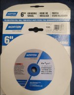
Caving to peer pressure,lol , i gave an AO wheel a shot. It didn't go so well. AO itself not being the problem. The problem i think was my wheel choice, but more importantly the angle of my dressing being a hair off.

I'll post more details and pics when I get back.
 
I wanted to give an update on my AO wheel experiment, plus ramble on a bit. . .

I really should have used an AO wheel. I know this. I've run hardened tool steel on a surface grinder with AO wheels. It cut and had a nice finish. Surely AO should cut hardened cast iron ways.

I should also note that in years past when researching wheels for my grinders, many different generations of guys, and different generations of forum posts. . . that AO for ferrous metals was mentioned enough to be a mantra, and maybe CBN wheels now-a-days. So when EG and Eric (eKretz) mention AO you can be sure they know, both experienced and qualified guys.

Also grit, so many times I've seen recommendations for 60 or 46 grit. And achieve very nice finishes with those grits. This may seem counter intuitive, if you take a course piece of sandpaper and scratch a metal surface, it will leave scratches. But fine piece of sand paper may polish or brighten a surface. However, in grinding, course wheels seem to perform better than fine wheels. I believe it has to do with material removal, or heat tranferance, or heat removal, but for some reason the course wheels seem to do very well and have nice finish, verse finer grit wheels.

So on to my first mistake. I attempted a 100 grit AO wheel. I'm unsure wheel hardness, and in truth, I don't know how to apply or factor wheel hardness, its a hole in my knowledge base. As I have probably .010" of more depth to cut, I thought I'd experiment to see if I could achieve a finer finish, hence the 100 grit.
605.JPG

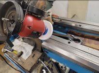
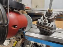
Wheel mounted. I dressed like I did in post 221, with the tip of dresser contacting wheel at 3 oclock.
608.JPG

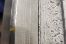
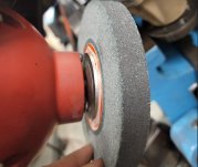
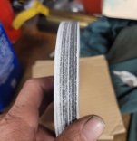
Problem. With this wheel I am now having a ridge in the middle of way surface, running the entire length of ways. I can feel it with my finger tip:
610.JPG

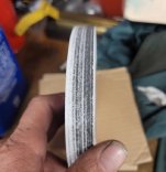
And we can see the contact pattern of wheel. The result is the same if your tram is off on a vertical mill, it leaves a line on over lapping passes:
612.JPG

I believe the reason is my crossfeed ways mounted to sled. I did a decent job of getting level and perpendicular to ways, but I think I may be a couple degrees off perpendicular. And by dressing wheel at the 3 oclock, I've transfered that inaccuracy.

584.JPG

Initially, the green silicon wheel contacted the same. But as Eric mentioned, they wear in quicker, or its softer. I never cut grooves with the green silicon, and the wheel conformed to the way surface in a reasonable time so that I gained full contact. We can see the full contact of green silicon here:
609.JPG

That was not planned on my part, I kind of dumb-lucked into that. If I had been dressing at 6 or 12 oclock, I think it would have reduced or eliminated the inaccuracy, I'd have to sort out how to hold the dresser though. Could maybe attempt to get crossfeed perfectly perpendicular to way. Or may roll with green silicon again, undecided yet.
 
Last edited:
As it sounds like you already know, 100 grit is way too fine a wheel. Get back to that 46. If you want to use a finer grit wheel, use it only for a final dusting at the end. You need to get your wheel dressing down so that alignment is correct or you will be fighting yourself the whole way through. If your green wheel wasn't dressed correctly and it was conforming to the surface, then the surface wasn't very straight. Sometimes silicon carbide does work better for cast iron, but I usually lean towards AlOx for hardened iron. For soft iron I like the SiC better because it will load an AlOx wheel like crazy, where the SiC wheel will sort of self-dress.
 
If your green wheel wasn't dressed correctly and it was conforming to the surface, then the surface wasn't very straight.
I dunno, monsewer. Was reading this and thinking. Apparently the existing ways were sort of acting as a crush roll on his soft-bond green wheel. Maybe, if he can't get an accurate dress, this is not such a bad thing. The ways themselves are acting as a dresser and it probably doesn't matter if they are at exactly the correct angle since he'll scrape the carriage and tailstock in later to match them.

An interesting situation, which may not exactly match normal thinking. Tex may have come up with a better method than the "right" one ....

Yes, it is, IMO. Because if the wheel is that soft, it will be continually dressing itself as he goes. It will never result in a straight surface as he adjusts the wheel over with his cross slide setup. Lots of dips and swerves will be the result. If he were spanning the entire way in one grind without moving the slide, maybe. Even then it would probably result in some twisting, especially near the beginning of the grind. The difference with the AlOx wheel is that he can see the defects easier because the wheel is holding its form better. With the SiC wheel I believe they will still be there but it's less noticeable, more blended together and - perhaps - only in the part of the way nearer the start of the grind. Still not good. And you don't want to scrape in an oddly shaped surface...or at least I sure wouldn't - especially as I think he would find that the print changed from the area where the grind started to the area that the wheel wore in. Sounds like a nightmare scenario to me.
 
I dont hnow what finish is Ideal for being smooth enough but not be abrasive to other sliding parts.
It seems that a surface that retains a film of oil would be what you want. It may be microscopic porosity. Or is a glass finish better?
 
Yes, it is, IMO. Because if the wheel is that soft, it will be continually dressing itself as he goes. It will never result in a straight surface as he adjusts the wheel over with his cross slide setup. Lots of dips and swerves will be the result. If he were spanning the entire way in one grind without moving the slide, maybe. Even then it would probably result in some twisting, especially near the beginning of the grind. The difference with the AlOx wheel is that he can see the defects easier because the wheel is holding its form better. With the SiC wheel I believe they will still be there but it's less noticeable, more blended together and - perhaps - only in the part of the way nearer the start of the grind. Still not good. And you don't want to scrape in an oddly shaped surface...or at least I sure wouldn't - especially as I think he would find that the print changed from the area where the grind started to the area that the wheel wore in. Sounds like a nightmare scenario to me.
I don't know a full answer to this. But I know you a little, and you've helped me a number of times. As a professional abrasives guy, your skill set and personal tolerances range is way tighter and higher quality than I can achieve. I'd say most professional grinder guys are regularly operating well inside of .0001" and maybe have a different critical eye than guys operating lathes and mills.

I own some grinders, and have dipped a toe in a little bit, but I find abrasives a wickedly deep and complicated rabbit hole. I think I'm not an entirely dumb guy, but I get truly lost in some of the more complex grinding discussions.

What I can tell you, I've had a lot of time to talk about, think, and probably over analyze this particular operation. The goal I hoped for was to be within .002"-.003" for the entire 88" of vee way. If achieved, it would give me amazing accuracy at the tool tip, accuracy this machine probably hasn't seen since the late 1950's.

Did you ever do a job, or run a series of passes and just be watching the work, and it was going like what you expected and hoped for ? You didn't mic or measure yet, but you kind of just know its going right. That's the exact feeling I've had as I've been running passes on this surface. I've mic'd all over this lathe bed prior to, and I'll check after as well, but my knee jerk reaction is I think I may beat that goal and be inside .002". Surface finish itself ? I'd like to improve it, but I don't think I'm too far off. I think I'm very close to something very nice.

Prior to trying the AO wheel, when running the SiC wheel, I stopped at one point and on a small spot i shot wd-40 and worked the surface with a block of wood and fine sandpaper. I thought it came up very nice.

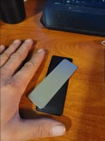
Several posts back, Eric mentioned flat honing to check. He didn't mention details of the flat hone, but I did pick up something:
613.JPG
A listing of it:

I'm not sure if that's what he had in mind, but its ultra fine, even the "medium" side. I'm thinking i'd use this if i'm working in millionth's. A diamond abrasive that you can just feel with a finger tip.
 
Last edited:
I dont hnow what finish is Ideal for being smooth enough but not be abrasive to other sliding parts.
It seems that a surface that retains a film of oil would be what you want. It may be microscopic porosity. Or is a glass finish better?
There are different schools of thought on this. Did you ever see a Bridgeport where the visible ways have beautiful flaking/scraping ? Some go that way, but many machine rebuilders frown on that.

Machine rebuilders that I happen to like, prefer smooth visible ways. With the pretty scraped and flaked bearing surfaces on the hidden and protected surfaces.

In this case, smooth bed ways. But carriage and tail stock scraped and flaked to provide oil retaining bearing surface. With both of those items being protected by facing down and way wipers. Part of the idea being, exposed and visible surfaces could potentially catch and hold grit or very fine debris, if they were scraped or flaked.

How smooth should the exposed surfaces be ? I'm not sure I can answer that with an exact number. But If dealing with a worn bed with wear lines, I think getting it smoother than that might help :D.
 
Last edited:
Looking to correct the dressing angle problem now.

I dressed at what I'm calling 3 oclock:
597.JPG

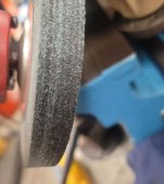
Looking at wheel contact. The blackened portion was toward rear of lathe. Due to the contact looking like this, I presume the blackened portion to be a slightly larger diameter than the untouched white portion. This occured by dressing at 3 oclock with cross slide being a degree out of a true 90 degree perpendicular angle to bed ways:
612.JPG

Because I dressed at 3 oclock, for the black portion to be a larger diameter, I would need to basically leave dial side of cross slide pinned where it is, but move rear side of cross slide toward tail stock end a degree or two, to correct the inaccuracy. Looking at old pic for a visual of that:
614.JPG

The tough part is, if I mount a dial indicator on grinder or compound, I don't have a perpendicular surface to sweep the indicator across, or any easy way to accomplish that.

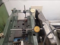
What I can do is mount two dial indicators, one on both bed ways. One indicator on dial side of cross feed way, the other on rear side of cross feed way. With that I could ensure that I am pivoting on dial side, while moving rear side. Maybe move rear side in .010" increments, dress wheel, run a pass, and check wheel contact. This would get me closer to true perpendicular, but it'll be time consuming, and I'd still be guessing a bit as to when I'm truly perpendicular.

I think I may try to correct that perpendicular angle as mentioned. But I also believe I have a way to dress at 6 oclock, though the set up will be a little ugly.

In other news, the only white AO 6"x3/4"x1" wheels in 60 or 46 grit I can find are in the area of $300. I'm probably not going to do that. I did find a 46M wheel that appears brown, I'll have that probably mid week this week. If I get any progress done in the meantime, it'll be with the SiC wheel.
 
Last edited:
Correction on the perpendicular angle turned out easier and a little quicker than I imagined. Though I still have one more adjustment I think.

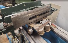
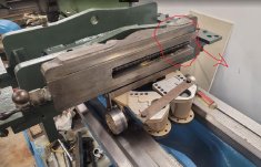
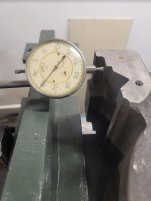
Re-looking at it, I decided to mount the two dial indicators on the sled itself. This provided better flat surfaces on the cross feed ways of grinder:
615.JPG

I have 4 bolts holding the cross feed way. I left the bolt on dial side tight, and loosened the other 3. Using a pry bar I nudged rear side toward TS end. I meant to move it .010", but over shot to about .016", and when I tightened bolts it moved to a total of .020".
616.JPG

As I was totally guessing, I dressed wheel and figured I check what that .020" gave me. It was too much. The contact pattern moved to the other side of wheel, though less severe. I loosened cross feed again, and shoved rear side back a little, and when tightened I had moved back by .0075". Moving back that .0075" still left me plus .0125" toward TS end. I dressed and ran a pass again. This got me very close to near full contact across wheel surface. I think I need to move .001" more towards the TS end with rear side of cross feed, which should put me at a total of .0135". Current pattern on wheel after a dress and a pass:
617.JPG
 
I have often considered doing this to my lathe, but I have never been able to figure out how to do the full length of the bed. In every way I have considered, I could grind all but about 18" of the bed, but the sled would prevent me from grinding the portion under the sled and away from the grinding wheel. What is your solution?
 
I have often considered doing this to my lathe, but I have never been able to figure out how to do the full length of the bed. In every way I have considered, I could grind all but about 18" of the bed, but the sled would prevent me from grinding the portion under the sled and away from the grinding wheel. What is your solution?

Great question. The sled currently rides on tail stock ways. We can't grind TS ways, while still using those ways as our guiding path. I have a solution, but it won't be in the manner that the manufacture, nor a specialized grinding shop may do.

I should mention that I am not intending to grind tail stock vee way. I do intend to grind the TS flat way though, as it got tore up from that short section on carriage. I'm also grinding carriage flat way. And the two unused flats on each bed rail, those two simply for looks, as someone thought they'd make a great anvil:
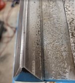
593.JPG

Looking at an old pic for visual aid. Carriage vee way is 88" long on mine. If measuring that 88" from TS end toward headstock, we know the carriage itself can not reach the full 88" end on headstock side, its stops several inches short.
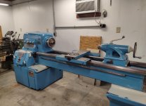
1.jpg

So for carriage itself, I dont need to grind the full length of bed on the carriage flat way. For carriage flat way, I will measure 88" from TS end, and mark that carriage flat way adjacent to carriage vee way, on other side of headstock.

Problem. With surface grinding, the grinding wheel can not start in the middle of the work, nor reverse course in the middle of a pass. The grinding wheel must start before touching the work, and finish its pass off the work.

Solution: A relief must be cut so that wheel can start(or finish a pass) without touching work. In the case of carriage flat way, I think carriage flat way needs to be ground .015"-.020". Measuring from TS end, I will grind a relief between the 88" and 90" mark. I will grind that 2" relief about .025"-.030" deep. The wheel will start inside the relief as I begin to make my passes for carriage flat.

Now on toward your real question, the tail stock ways. . . A little more complicated, but requires the same solution. Relief cuts.

Knee jerk reaction, the end solution may not seem as desirable. But if you really consider the difference between what the carriage does, and what the tail stock does, this will be very effective.

Difference between carriage and tail stock operation. Carriage carries the tool tip, its flow and movement must be smooth and have perfect symmetry, or the results will transfer to the work being cut. Luckily, we have no reliefs cut in the total path of carriage, so it will have this symmetry. Tail stock does not need this so much. Tail stock is moved and locked down. What we need is tail stock to have consistent height and alignment to headstock spindle. So a relief cut somewhere in its operational path won't matter to the actual work, as long as the TS way maintains the TS height and alignment.

Cutting TS ways can not be done using TS base, nor using the same ways you are cutting. To cut TS ways we must use carriage and carriage ways, transferring grinder to carriage.

Problem. Carriage has limited range/reach in both directions. And if mounting grinder to carriage to either headstock side or tailstock side, we can not complete a full uninterrupted pass of TS ways.

Solution. Don't grind TS ways under head stock, plus we will need to cut two reliefs.

The first relief will be directly in front of headstock mounting. With head stock removed, we can see the tattoo mark where it sat. First relief cut there. Its under chuck, and with lathe complete, tail stock itself can not physically reach this first relief cut anyway. Note the line in front of bolt hole, thats where first relief cut will begin:
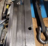
600.JPG

Unfortunately, the second relief will need to be cut in the path of TS operation. To accomplish grinding TS ways, the grinder will need to be mounted on TS side of carriage first. A short section ground at TS end of bed. Then grinder swapped toward headstock side of carriage, where the longer uninterrupted grinding path will be ground from relief at headstock to the relief I need toward the TS end. Carriage is 25" in wing span. I need to actually set up grinder on carriage to know an exact number, but I suspect the second relief to be cut somewhere at 24"-30" from end of bed on TS end. *Edit: That 2nd relief serves double duty. Its the grinder starting point for working short section at TS end of bed. And the stopping point from headstock toward TS end.

I will attempt to keep that relief short, maybe 1" long. Also the depth of second relief to within .001". Example, if I need to remove .015" from TS way. I will try to cut depth of relief to .0155"-.016".

Upon total lathe completion, this will leave a 1" section, .001" lower than the rest of TS way. As the bed is long, most of my TS operation will occur past that mark and toward head stock anyway. If I have to cross that section, or even lock TS down over it, so what ? It won't affect actual operation, as I will have ground way to the same height, to either side of the 2nd relief. It'll be a minor blemish which I can live with. I may fill that 1" blemish/low spot with epoxy.
 
Last edited:
Texasgeartrain,

The end of your bed looks like someone used it for an anvil. My L & S along with many other old lathes I've been around over the years had that same appearance to it. My assumption is, it's from many years of neglect of not keeping the "6's" and "9's" soaked in coolant, cleaned off the bed. The coolant was probably not at an ideal PH level, which caused chemical/metallic reaction of the two metals. And of course, I'm sure there were stray electrical currents passing through the machine bed from improper grounding. Just saying,IDK for a fact. Just sounds good. Over time these "puddles" made craters in the bedways.
 
Many years ago, when my dad used to send out machine tools for rebuilding at a shop in Dallas, lathes in particular. They would not disturb the ways under the headstock. Just like you said, cut/grind a relief right in the ways in front of the headstock. That would give a place for the planer tool to drop out into. For bed ways that were ground, I never saw them cut any kind of relief in the bed ways in front of the headstock. The grinding wheel would stop on a dime at the same place on every stroke on that planer they used.
Usually, the tailstock ways don't wear near as much as the carriage ways do. I know on my last lathe rebuild, which is still on going, the bed ways had about .007-.008" wear on them. Basing this on using a straight edge straddling the worn area of the bed near the head stock. Likewise, the tailstock ways I wasn't able to detect any wear. If there is and I'm sure there is, it's less than a .001". From this I will be using the tailstock ways just like you're doing to grind the ways on my Sheldon lathe bed. Just waiting for a decent week to drag it outside to do. I have everything ready to grind.
Oh, it's looking good, it's just a long drawn-out process of doing. I think I spent over a month grinding on the L & S bed myself. Ken


Back
Top