What's new
What's new

Lineshaft Machine Shop Photos

Tuckahoe Steam and Gas Association machine shop museum. This is where I spend most of my Saturdays. In this picture you can see the black belt leading down to our early 1900s Fellows gear shaper. We are trying to get this machine running from the line shaft for our show coming up July 6th through 9th. The tan belt to the left runs the Lucas horizontal boring mill.
How do you guys ancore your hangers into the ceiling? Are they lag-bolted into joists, through bolted, have reinforcing boards on the other side, etc.?

When you have as much iron hanging from the ceiling as in these old shops, and then consider the rotation and tension forces in play, I'm curious when a standard but proper ceiling and roof structure is enough and at what point you have to think different about it.
 
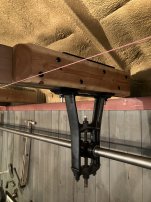
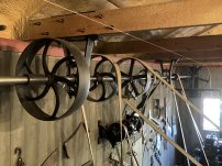
Maybe this has been posted before? A good one from Shorpy:

1902. "Screw Machine Department, National Cash Register, Dayton, O

Cool picture. We had an old Cleveland automatic lathe that used 12” pipe for cams on the drums. It feed stock, stoped it, drilled it, chamfered and parted until the bar ran out. I wish I would of taken a picture.
 
How do you guys ancore your hangers into the ceiling? Are they lag-bolted into joists, through bolted, have reinforcing boards on the other side, etc.?

When you have as much iron hanging from the ceiling as in these old shops, and then consider the rotation and tension forces in play, I'm curious when a standard but proper ceiling and roof structure is enough and at what point you have to think different about it.
Since the hangers will rarely fall on ceiling rafters, we span them with 2x material forming a u-channel and the use threaded rod up though the u-channel. As you can also see from the picture, we sandwich 2x6 between the hangers and the ceiling for extra structure.
 
How do you guys ancore your hangers into the ceiling? Are they lag-bolted into joists, through bolted, have reinforcing boards on the other side, etc.?

When you have as much iron hanging from the ceiling as in these old shops, and then consider the rotation and tension forces in play, I'm curious when a standard but proper ceiling and roof structure is enough and at what point you have to think different about it.
I through bolted ours, with the bolts beside the trusses so as to not have to drill the bottom chords. Liked the look too. If I did it again, I might just lay a 2 x 10 on top of the bottom chords and attach the hangers to that- lots less effort- but the hangers wouldn't be as proud and visible. In the new addition part of our shop, the trusses are turned 90 deg, so I ended up bearing some 4 x 6s on the outside wall and attaching the hangers to them. Had the truss designer beef up the trusses in the original shop to carry the added load, builder screwed up on the addition and didn't get it done...
 

Attachments

  • IMG_8931.JPG
    IMG_8931.JPG
    2.2 MB · Views: 18
  • IMG_8932.JPG
    IMG_8932.JPG
    2.9 MB · Views: 17
  • IMG_8933.JPG
    IMG_8933.JPG
    3.3 MB · Views: 16
  • IMG_8942.JPG
    IMG_8942.JPG
    2.5 MB · Views: 16
  • IMG_8943.JPG
    IMG_8943.JPG
    2.4 MB · Views: 16
  • IMG_8946.JPG
    IMG_8946.JPG
    1.5 MB · Views: 15
  • IMG_8950.JPG
    IMG_8950.JPG
    3.4 MB · Views: 18
  • IMG_8951.JPG
    IMG_8951.JPG
    1.6 MB · Views: 18
Last edited:
My blacksmith shop is a 24' X 36' pole barn with a dirt floor, steel skin and roof with trusses. When thinking about line shaft support I was concerned about weight and possible vibration on the trusses. I set six 6" X 6" rough sawn vertical posts in concrete, in two rows of three posts each. To the side of each row of three posts I clamped and leveled another horizontal 6" X 6" and fastened it to each post with 3/4" rod hand threaded for a snug fit. The horizontal 6 X 6 on the second set of three posts was leveled with the first horizontal 6 X 6. Now I had two support surfaces about 15' apart that were leveled in both directions that were not attached to any part of the building. By using milled timbers laying across these, I could install bearing hangers that would be level without adjusting. So far nothing has shifted.

Attached is a photo that I took a couple of years ago of the main shaft which is 18' long.

Bob
WB8NQW
 

Attachments

  • DSC00061.JPG
    DSC00061.JPG
    3.5 MB · Views: 29
I think it may be some kind of metal parts tumbler for cleaning up castings and stampings with abrasive or other media.
Similar but larger than those used for polishing gem stones.
I find it a bit odd that the belt is directly on the drum rather than by a pulley on the end of the shaft but that might make it easier to change drums with coarser or finer media as long as the base is anchored to the floor and the bearings hold back against the belt tension.
There are some other do it yourself examples on YouTube .
Jim
 
Looks to me that theres something mounted to that stand that serves a purpose . Could it be some sort of early 2nd op's machine ?
animal
 
Here are some pictures of I took in 2010 at the Heritage Power Weekend of the pump factory shown in the video.
I had posted them in another thread but they are now held hostage by the then photo host.
The pump handles were finished by hand .
The story about the pump factory
A finished pump
More history
The drill in operation
P.S. here is a link to the Cumberland museum's current website.
 

Attachments

  • Cumberland + others 008.jpg
    Cumberland + others 008.jpg
    322.7 KB · Views: 10
  • Cumberland + others 095.jpg
    Cumberland + others 095.jpg
    322.1 KB · Views: 11
  • Cumberland + others 096.jpg
    Cumberland + others 096.jpg
    325.4 KB · Views: 10
  • Cumberland + others 097.jpg
    Cumberland + others 097.jpg
    313.7 KB · Views: 10
  • Cumberland + others 102.jpg
    Cumberland + others 102.jpg
    328.4 KB · Views: 10
Last edited:


Back
Top