What's new
What's new

Understanding Lathe/Mill Cutter Comp Startup Moves

I suppose the value-proposition of cutter comp is that the investment in time required to understand how to use it will be worth never having to figure out the geometry again.
Then buy a hot dog cart and you'll never have to deal with geometry. Sorry, but all that nc is is one giant geometry problem. If one is scared of geometry, then one is at a disadvantage right from the beginning.

Actually, it's pretty simple. If you want the tool to go exactly where you say, use centerline programming. If it doesn't bother you that the thing hops around like a drunken frog, use cutter comp.

sinha said:
I talk with reference to i-series Fanuc only.
Understood, but some people don't know that there's so much variation in controls. That's why I think it's better to qualify blanket statements ....
 
Just a slight revision to this. The length of the compensation move you want/need depends on how your tool path is created, not necessarily on the size of the cutter. Center compensation (none), CAM compensation, Control compensation, etc. If the toolpath is offset from the edge (CAM compensation), then the length of the move only needs to be larger than any wear adjustments you want to make. The control has no idea (and doesn't care) how large of a cutter you are using.

For example, I can use a 1/2" cutter with an offset path (CAM compensated), and using a 0.010" compensation move is fine (as long as I don't try to put more than 0.010" of wear compensation in).
Excellent point! Thank you!
 
I tried it when you were in diapers. It's shit. Also your claim about tool nose wear is silly. Sorry, charlie, ain't gonna fly.
Okay. You do you. It's a whole world of offset and geometry tuning just waiting to be exploited. I can tune X and Z values for wear to hit a target but, not R huh?
 
If one is scared of geometry, then one is at a disadvantage right from the beginning.
weeell I am not any more "scared" of geometry than I am of, say, math, but I still often use a calculator instead of paper and pencil.

I get it - you are infinitely more comfortable calculating the tool path and programming as such instead of using cutter comp and maybe I will be, too! But I figured it was appropriate to at least LEARN how the feature is intended to be used... Thank you for your contributions to this thread (sincerely!)
 
I get it - you are infinitely more comfortable calculating the tool path and programming as such instead of using cutter comp
It's not "comfort" as much as, I want the damned thing to do what I say. Exactly what I say ! Other people are happy with an approximation* and that's fine for them but I'm too ocd for that :)

*Yes it's an approximation. As a user you don't even know how the tool goes around a corner with cutter comp. Some controls do it properly, connecting the lines with a radius, while others apparently just extend the lines. Unless you can read the control's exec, you don't even know what it's doing. Yeah, i know. Picky picky picky. Some of us are.
 
It's not "comfort" as much as, I want the damned thing to do what I say. Exactly what I say ! Other people are happy with an approximation* and that's fine for them but I'm too ocd for that :)

*Yes it's an approximation. As a user you don't even know how the tool goes around a corner with cutter comp. Some controls do it properly, connecting the lines with a radius, while others apparently just extend the lines. Unless you can read the control's exec, you don't even know what it's doing..
I don't know where you get this from. I could draw out on paper exactly what the cutter is going to do. Of ALL the people who should know this, YOU should know.

In the days of old, there was this CAD system written by Lockheed called CADAM. The NC package in there showed and animated exactly what cutter comp was going to do, as it did it. When you were done, you could animate the bouncing ball (cutter circle) around the part. The cutter was always two elements behind. We called it walking the dog: a leash going back two elements as it figured out where you were going around the otherwise abstract lines.

First programmed move: the tool is centered at the start point. Second programmed move (G1, 2 or 3) it now has some idea which side of the line it needs to be on (left or right) but, doesn't know how far to under-run or over-run the intersection. Program the third move and now it knows exactly where it needs to be. Congratulations! You've established cutter comp!

Drag it around or across the part, one move at a time. At the end give it two moves off the part and you've returned to the cutter being centered over the last point. The last move is where the move from compensated-to-CL happens. It happens in a straight line. If this is beyond the part, it can be done in one move without plowing through your part. Because of the tapered change as the last move executes, most CAM systems will output an arc as a transition and then a line to finish (the arc will be compensated away from the part and then the line will taper back to zero.

That tapered transition is why it has to be more than one radius of distance to accomplish what it needs to do. If the move is shorter, it doesn't know where to put the radius relative to all the subsequent moves. This is a lot of words to describe what is much easier to draw out on paper. Maybe there are some animations out there that describe it. It's not that complicated and it's truly not doing whatever the heck it feels like.
 
I don't know where you get this from. I could draw out on paper exactly what the cutter is going to do.

Excuse me NO. You do NOT know what the control does as it goes around a chamfer. You do NOT have any clue what's inside that control. I have found two different methods somewhat described, but nobody outside of the control builder really knows what the control does.

Of course I know where the tool goes when I tell it where to go, but using cutter comp you do NOT know what's going on.

Not that it is the end of the world, but them's facts. Facts count to some of us. Or me, at least.
 
Excuse me NO. You do NOT know what the control does as it goes around a chamfer. You do NOT have any clue what's inside that control. I have found two different methods somewhat described, but nobody outside of the control builder really knows what the control does.
Are you talking about the Yasnac vs Fanuc retract at the end of a canned cycle? Meh. Like everything on here, I like discussing this with you because it makes us all better but, we're really picking the fly shit out of the pepper here. Get the ramp-off move away from the part and it's fine.
 
You do NOT know what the control does as it goes around a chamfer.
It is explained in detail in Fanuc manuals. A few things are parameter-dependent. That also is explained with explanatory sketches.

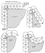
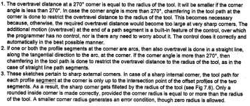
Broadly, there can be two types of motions at an external corner: the tool may rotate about the corner, or it may over-travel. Fanuc uses over-travel method, with an additional chamfering motion in some cases. Some cases are shown in the figure below.
1703271570041.png


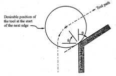
Some controls use rotation method:
1703271800246.png
 
To be technical about it @EmGo is correct, you don't know exactly what is going to happen, it is calculated with trig in the control, as is mentioned above the various different rules on those calculations, so.

And in previous posts I have mentioned that I have had a control consistently screw up randomly on the trig help when calculating a feature and instead of doing something like a radius on a corner, it would do a full circle and then the radius,
we ended up having to program direct, but more so turn off trig help on the control(thanks for the help, but no thanks!).

And yes when you zoomed in and check CAM it was fine, checked Gcode it was fine, checked on control preview you could zoom far in and see the little circle rendered. :mad5: :bawling:
 
I suppose the value-proposition of cutter comp is that the investment in time required to understand how to use it will be worth never having to figure out the geometry again.

^^^This^^^

Seriously, just ignore Emgo and the whatever fucking bug that's up his ass about TNR on a lathe.
You truly only need to figure out the comp-ON and OFF moves, the rest - in today's controls anyway - is pretty much identical.
Figure it out once, you'll never look back and likely will never write a program without it.
 
To be technical about it @EmGo is correct, you don't know exactly what is going to happen, it is calculated with trig in the control, as is mentioned above the various different rules on those calculations, so.

And in previous posts I have mentioned that I have had a control consistently screw up randomly on the trig help when calculating a feature and instead of doing something like a radius on a corner, it would do a full circle and then the radius,
we ended up having to program direct, but more so turn off trig help on the control(thanks for the help, but no thanks!).

And yes when you zoomed in and check CAM it was fine, checked Gcode it was fine, checked on control preview you could zoom far in and see the little circle rendered. :mad5: :bawling:
Yes, and I have seen this exact problem without using cutter comp. It's a G02/G03 problem with using R instead of IJK and zigging when it should have zagged. You zoomed in, saw the error and...okay? You moved on.

Throwing out the baby with the bath water and all that.
 
So can you turn from X0.
3) In turning centers, cutter comp is invoked similarly to mills - a G01 line perpendicular to the surface. It is disengaged the same way, a single G01 line off of the part.
So, I usually program an OD like this:

G0 G99 T0404
X8. Z8. M8
G96 S800 M3
X.75 Z.12
G1 G42 Z0
X1.25 R-.032
Z-.5
X1.75 R-.032
Z-1.
G40 X1.875 M9
G0 X8. Z8. M5
M30
%
sooooo lets say you are using a .032" rad insert. When you move to X.75 Z.12 the "6 o'clock" location of your insert rad will be at X.75 and the "9 o'clock" location of your insert rad will be a X.75+.032(x2)...relative to the centerline of the spindle. So when you do the G1 G42 Z0 move will the machine think you are at X.75 still or X.75+.032(x2)...like what would the POS screen say? By way of example, will this leave a tit?:

X0. Z.100
G1 G42 Z0.
X1.000
blah
blah

If so, and you wanted to turn the entire profile from X0., could you either 1) include an "X0." word in the G42 move or 2) begin below the centerline by at least the radius of the tool?

I assume changing directions with cutter comp on is a nono? For instance:

X2.000 Z.100
G1 G42 Z0.
X0.
X1.000
blah
blah

Thank you, again, for all your help! I'll never look at chamfers/tapers/radii the same way again, haha!
 
The old Fanuc Type "B" compensation used a G39 code to get around sharp corners. Is anyone here besides me old enough to remember this code?
yup. Plus the G45 through G48 for radius single extension and reduction and radius double extension and reduction. You ain’t the only old timer here :codger:.

Kind of back on topic, I learned lathe programming on controls that did not have radius comp. It’s so easy to comp the path that almost 50 years later if I had to program a lathe I’d just comp the path.
 
Are you talking about the Yasnac vs Fanuc retract at the end of a canned cycle?
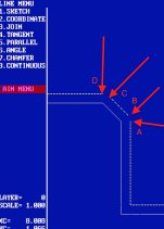
No. I am talking about this

sample.jpg

Solid path is the part, dash path is the cutter path. This is THE SAME path that you get using cutter centerline or tool nose comp. Exactly the same.

What is different is, when you write the toolpath yourself, you connect those non-contiguous spaces WITH AN ARC. A->B, C->D. Yeah I got carried away annotating :)

The reason you do that is, with an arc the tool never leaves the part surface. There is no burr of any kind.

When you allow the control to do that, you get what it thinks is fine. Most people here arguing, e.g. Donkey, don't even know this is happening. The control CAN do an arc or it CAN just extend the lines of the part. Extending part surface lines is not as good. Period. It may not leave a noticeable burr, but it DOES leave "a" burr. Given two parts each done the different way, you can feel it. Whether that matters to you or not is your choice.

Also, you don't know which method the control is using. sinha says fanuc does "a", vanc and others say "no it can do b", who the hell knows what a yasnac or mach iii or osp okuma or mazatrol do ? But if you write the program yourself and tell the cutter exactly where to go, that's what it does. Period, end of story.

Back to the point, does it matter ? Does it matter if I wear a clean shirt and socks ? Do I have to take a shower every day ? I could easily go four or five days, it's only a little stink, if no one gets too close they'll never know.

To each his own. I don't much care if Seymour stinks, I don't go over there. But I do think people should know what's going on under the covers so they can make an informed decision. Choice is better if you at least know what you're choosing between.
 
It is explained in detail in Fanuc manuals. A few things are parameter-dependent. That also is explained with explanatory sketches.

Broadly, there can be two types of motions at an external corner: the tool may rotate about the corner,
Yes there are two ways to do sharp turns. (actullay a third outside circle trip also).
One may bend or touch the corner a tad bit but is faster. The second spends time in the air and chip load goes to shit. Tradeoffs.
Tis wierd stuff.
 
Since arguing for lathe TNR or mill cutter comp is a hill I'm willing to die on any day ...

What is different is, when you write the toolpath yourself, you connect those non-contiguous spaces WITH AN ARC. A->B, C->D. Yeah I got carried away annotating :)


Please, do tell us how programming a connecting radius without comp is any different than doing so with comp?

As for anyone who does not know ahead of time that the control extends the toolpath to a sharp corner and thereby leaving the part, will know with absolute certainty exactly 2 seconds after the part comes off the machine.
Then he/she can sit down, figure out the logic behind it and never ever make that same mistake again.
One notable difference however. When he/she programs a .008R for the corner using TNR comp, he/she can be certain that the result will be a .008R in that corner.


Back
Top